H-IM-CU February 2023 Part No. 25008101
H-IM-CU-0223 | Version 008
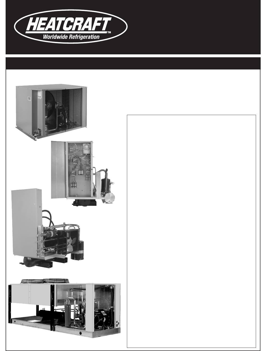
Condensing
Units
Installation and
Operations Manual
Table of Contents
General Safety Information..........................................................................2
Inspection ..........................................................................................................2
Warranty Statement .......................................................................................2
DOE Walk-In Cooler Freezer AWEF Set Points .......................................2
Space and Location Requirements ..........................................................3
Condensing Unit Rigging and Mounting ...............................................4
Remote and Water Cooled Condensing Units Requirements .........5
City & Tower Water Connections ................................................................ 5
Head Pressure Control ...................................................................................6
Phase Loss Monitor .........................................................................................7
Polyol Ester Lubricants ..................................................................................7
Refrigerant Piping ...........................................................................................8
Suction Lines .....................................................................................................8
Liquid Lines .......................................................................................................9
Unit Cooler Piping ...........................................................................................9
Line Sizing .................................................................................................10-17
Check System Pressure ...............................................................................18
Evacuation and Leak Detection .............................................................. 18
Refrigerant Charging Instructions .......................................................... 18
Refrigerant Flooding Charge ..............................................................19-22
Field Wiring ..................................................................................................... 23
Check Out and Start Up ............................................................................. 23
Operational Check Out ...............................................................................24
General Sequence of Operation .............................................................25
Refrigeration Cycle ....................................................................................... 25
Defrost Cycle .................................................................................................. 25
Copeland Demand Cooling ...................................................................... 25
Electric Defrost Troubleshooting ............................................................26
Variable Speed Motor with Orbus Controller ............................................ 26
System Troubleshooting Guide ............................................................... 28
Pressure Fan Cycling Recommended Settings ..................................29
InterLink™ Replacement Parts ........................................................................ 29
Preventive Maintenance Guidelines ......................................................30
Typical Wiring Diagrams ......................................................................31-35
Replaces February 2022
2
WARNING: Inspect and check system pressure rst and safely discharge dry air or nitrogen holding charge
before charging the system with refrigerant.
DO NOT OPEN THE SYSTEM OR REMOVE SCHRADER CORE(S) WITHOUT CHECKING THE PRESSURE FIRST!
The forgoing is in lieu of all other warranties, express or implied,
notwithstanding the provisions of the uniform commercial code, the
Magnuson-Moss Warranty - Federal Trade Commission Improvement Act, or
any other statutory or common law, federal or state.
SELLER makes no warranty, express or implied, of tness for any particular
purpose, or of any nature whatsoever, with respect to products manufactures
or sold by seller hereunder, except as specically set forth above and on
the face hereof. It is expressly understood and agreed that SELLER shall not
be liable to buyer, or any customer of buyer, for direct or indirect, special,
incidental, consequential or penal damages, or for any expenses incurred by
reason of the use or misuse by buyer or third parties of said products. To the
extent said products may be considered "consumer products," As dened
in Sec. 101 of the Magnuson-Moss Warranty - Federal Trade Commission
Improvement Act, SELLER makes no warranty of any kind, express or implied,
to "consumers," except as specically set forth above and on the face hereof.
The following conditions should be adhered to when installing this unit to
maintain the manufacturers warranty:
a) System piping must be in accordance with good refrigeration
practices.
b) Inert gas must be charged into the piping during brazing.
c) The power supply to the unit must meet the following conditions:
A. Three phase voltages must be +/- 10%
of nameplate ratings. Single phase must be
within +10% or -5% of nameplate ratings.
B. Phase imbalance cannot exceed 2%.
d) All control and safety switch circuits must be properly connected
according to the wiring diagram.
e) The factory installed wiring and piping must not be changed
without written factory approval.
f) All equipment is installed in accordance with
Heatcraft Refrigeration Products specied minimum clearances.
© 2023 Heatcraft Refrigeration Products LLC
Inspection
Responsibility should be assigned to a dependable individual at the job site
to receive material. Each shipment should be carefully checked against the
bill of lading. The shipping receipt should not be signed until all items listed
on the bill of lading have been accounted. Check carefully for concealed
damage. Any shortage or damages should be reported to the delivering
carrier. Damaged material becomes the delivering carrier’s responsibility,
and should not be returned to the manufacturer unless prior approval is
given to do so. When uncrating, care should be taken to prevent damage.
Heavy equipment should be left on its shipping base until it has been
moved to the nal location. Check the serial tag information with invoice.
Report any discrepancies to your Heatcraft Refrigeration Products Sales
Representative.
Warranty Statement
Seller warrants to its direct purchasers that products, including Service Parts,
manufactured by SELLER shall be of a merchantable quality, free of defects in
material or workmanship, under normal use and service for a period of one
(1) year from date of original installation, or eighteen (18) months from
date of shipment by SELLER, whichever rst occurs. Any product covered by
this order found to Seller’s satisfaction to be defective upon examination at
Seller’s factory will at SELLER’s option, be repaired or replaced and returned
to Buyer via lowest common carrier, or SELLER may at its option grant Buyer
a credit for the purchase price of the defective article. Upon return of a
defective product to SELLER’s plant, freight prepaid, by Buyer, correction of
such defect by repair or replacement, and return freight via lowest common
carrier, shall constitute full performance by SELLER of its obligations
hereunder.
SELLER shall have no liability for expenses incurred for repairs made by
Buyer except by prior, written authorization. Every claim on account of
breach of warranty shall be made to SELLER in writing within the warranty
period specied above – otherwise such claim shall be deemed waived.
Seller shall have no warranty obligation whatsoever if its products have
been subjected to alteration, misuse, negligence, free chemicals in system,
corrosive atmosphere, accident, or if operation is contrary to SELLER’s or
manufacturer’s recommendations, or if the serial number has been altered,
defaced, or removed.
MOTOR COMPRESSORS:
Motor compressors furnished by SELLER are subject to the standard warranty
terms set forth above, except products with LG model compressors which
will have warranty of two (2) years from installation or thirty (30) months
from shipment, " then continue on with that replacement should be made
from nearest authorized compressor wholesaler. The replacement motor
compressor shall be identical to the model of the motor compressor being
replaced. Additional charges which may be incurred throughout the sub-
stitution of other than identical replacements are not covered by this warranty.
An optional, non assignable, four (4) year extended compressor warranty
may be purchased within the boundaries of the United Sates of America,
its territories and possessions, and Canada. With this extended compressor
warranty, replacements are administered by an authorized compressor
distributor only. Replacements within the rst year of the warranty area
available through the distributor; the second through fth years, the purchaser
must submit a proof-of-purchase of a compressor and supply it to Heatcraft
Refrigeration Products Warranty Claims for reimbursement.
Seller makes no express warranties except as noted above. All implied
warranties are limited to the duration of the Express Warranty. Liability for
incidental and consequential damages is excluded.
LOP - 55°F
CM - 85°F
LVCM - 80°F
MP - 55°F
LUC - 55°F
Unloader Pressure Control
MT - Below 23°F SST LT - Below -22°F SST
WARNING: Refrigerant can be harmful if it is inhaled. Refrigerant must be used and recovered responsibly.
Failure to follow this warning may result in personal injury or death.
General Safety Information
1. Installation and maintenance to be performed only by qualied
personnel who are familiar with this type of equipment.
2. Refrigeration systems are typically pressurized with a holding charge of
dry air or inert gas. It must be evacuated before charging the system
with refrigerant. The system pressure must be checked rst prior to any
preparation work for evacuation. See Check System Pressure section on
Pg. 18.
3. Make sure that all eld wiring conforms to the requirements
of the equipment and all applicable national and local codes.
4. Avoid contact with sharp edges and coil surfaces. They are a potential
injury hazard.
5. Make sure all power sources are disconnected before any service work
is done on units.
Defrost Termination
Evaporator Superheat
6.5°F
Condensing Unit Head Pressure
LT-Revision A 100 psi
LT-Revision B 145 psi
MT-Revision A 145 psi
DOE Walk-In Cooler Freezer AWEF Set Points
Based on information currently available, following set points must be
adhered to for DOE AWEF test conditions (when adjustable):
Disclaimer: This communication is provided for informational purposes only
and is based on information that is subject to change and interpretation.
Heatcraft recommends customers review the applicable laws and
regulations to ensure compliance with regulations. For DOE regulations, see
US DOE Energy Eciency and Renewable Energy website for Walk-In Coolers
and Freezers at https://www.regulations.doe.gov/ccms
3
© 2023 Heatcraft Refrigeration Products LLC
The most important consideration which must be taken into account when
deciding upon the location of air-cooled equipment is the provision for a
supply of ambient air to the condenser, and removal of heated air from the
condensing unit or remote condenser area. Where this essential requirement
is not adhered to, it will result in higher head pressures, which cause poor
operation and potential failure of equipment. Units must not be located
in the vicinity of steam, hot air or fume exhausts. Corrosive atmospheres
require custom designed condensers.
Another consideration which must be taken is that the unit should be
mounted away from noise sensitive spaces and must have adequate support
to avoid vibration and noise transmission into the building. Units should be
mounted over corridors, utility areas, rest rooms and other auxiliary areas
where high levels of sound are not an important factor. Sound and structural
consultants should be retained for recommendations.
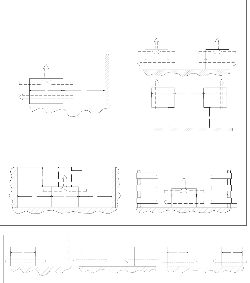
Space and Location Requirements for Air Cooled Condensing Units and Remote Condensers
Figure 1. Space and Location Requirements for Condensing Units
Units in Pits
The top of the unit should be level with the top of the pit, and side
distance increased to “2W”.
If the top of the unit is not level with the top of pit, discharge cones or
stacks must be used to raise discharge air to the top of the pit. This is a
minimum requirement.
Units Inside Decorative Fence
Fences must have 50% free area, with 1 foot undercut, a “W” minimum
clearance, and must not exceed the top of unit. If these requirements
are not met, unit must be installed as indicated for “Units in pits”.
Walls or Obstructions
The unit should be located so that air may circulate freely and not be
recirculated. For proper air ow and access all sides of the unit should be
a minimum of “W” away from any wall or obstruction. It is preferred that
this distance be increased whenever possible. Care should be taken to
see that ample room is left for maintenance work through access doors
and panels. Overhead obstructions are not permitted. When the unit is
in an area where it is enclosed by three walls the unit must be installed
as indicated for units in a pit.
Units Near Walls or Obstructions
Multiple Units Near Walls or Obstructions
* “W” = Total width of the condensing unit
Multiple Units
For units placed side by side, the minimum distance between units is the
width of the largest unit. If units are placed end to end, the minimum
distance between units is 4 feet.
W
MIN.
W
AIR FLOW
W
AIR FLOW
W
W
W
MIN.
W
AIR FLOW AIR FLOW
W
Clearance for multiple units placed side by side
AIR FLOW AIR FLOW
AIR FLOW
W
W
MIN.
W
MIN.
1 FT. MIN.
Clearance for fence enclosures
AIR FLOW
2W
MIN.
2W
MIN.
10 FT. MAX.
W
Clearance for units in pits
AIR FLOW
STACK
(SUPPLIED BY OTHERS)
W
W
MIN.
AIR FLOW
Clearance from walls or obstructions
AIR FLOW
CONFIGURATIONS BELOW ARE NOT RECOMMENDED
AIR FLOW
W
W
AIR FLOW
W
AIR FLOW
AIR FLOW
W W
AIR FLOW
SIDE VIEW
SIDE VIEW
SIDE VIEW
TOP VIEW
SIDE VIEW
4
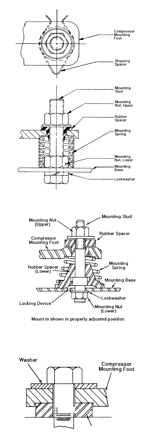
Figure 3. Spring Mount
Figure 4. Spring Mount
Condensing Unit Rigging and Mounting
Rigging holes are provided on all units. Caution should be exercised when
moving these units. To prevent damage to the unit housing during rigging,
cables or chains used must be held apart by spacer bars. The mounting
platform or base should be level and located so as to permit free access of
supply air.
Ground Mounting
Before tightening mounting bolts, recheck level of unit.
Roof Mounting
Roof mounted units should be installed level on steel channels or an I-beam
frame capable of supporting the weight of the unit. Vibration absorbing pads
or springs should be installed between the condensing unit legs or frame
and the roof mounting assembly.
Spring Mounted Compressor
Compressors are secured rigidly to make sure there is no transit damage.
Before operating the unit, it is necessary to follow these steps:
a) Remove the upper nuts and washers.
b) Discard the shipping spacers.
c) Install the neoprene spacers. (Spacers located in the electrical
panel or tied to compressor.)
d) Replace the upper mounting nuts and washers.
e) Allow 1/16 inch space between the mounting nut/washer and
rubber spacer. Mounting spring must not be fully compressed
when mounting nut is properly installed. See Figures 2 and 3.
Rigid Mounted Compressor
Some products use rigid mounted compressors. Check the compressor
mounting bolts to insure they have not vibrated loose during shipment. See
Figure 4.
Figure 2. Spring Mount
Figure 3. Spring Mount
Figure 4.
Solid Mount for Mobile or Deep Sump Application
Spacer
5
General Installation
The indoor compressor units are designed to be used with a remote
condenser. The water cooled units are similar, except that they have an
integral water cooled condenser. Inlet and outlet water connections are to
be made in the eld. On units having a compressor water jacket, incoming
water shall be routed through the jacket prior to entering the condenser. For
cleaning purposes, condenser end plates can be removed to give access to
the water tubes. Cleaning is accomplished by a simple spiral tool powered
by an ordinary electric drill. During installation, allow space for cleaning the
condenser. Commercial equipment of this type is intended for installation
by qualied refrigeration mechanics.
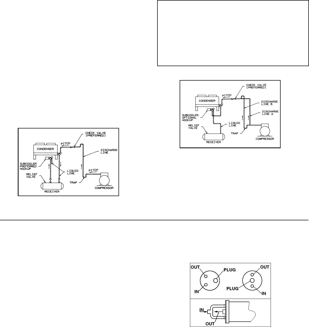
Typical Arrangements
Diagram 1 illustrates a typical piping arrangement involving a remote
condenser located at a higher elevation, as commonly encountered when
the condenser is on a roof and the compressor and receiver are on grade
level or in a basement equipment room.
In this case, the design of the discharge line is very critical. If properly sized
for full load condition, the gas velocity might be too low at reduced loads
to carry oil up through the discharge line and condenser coil. Reducing the
discharge line size would increase the gas velocity suciently at reduced
load conditions; however, when operating at full load, the line would be
greatly undersized, and thereby creating an excessive refrigerant pressure
drop. This condition can be overcome in one of two of the following ways:
1. The discharge line may be properly sized for the desired pressure
drop at full load conditions and an oil separator installed at the
bottom of the trap in the discharge line from the compressor.
2. A double riser discharge line may be used as shown in
Diagram 2. Line “A” should be sized to carry the oil at minimum
load conditions and the line “B” should be sized so that at the
full load conditions both lines would have sucient ow velocity
to carry the oil to the condenser.
City & Tower Water Connections
In the refrigeration industry “City” and “Tower” are designations of
temperature and ow conditions, not applications. The term “City” refers
to operating conditions where incoming water is 75˚F, and condensing
temperature is 105˚F. “Tower” refers to a higher temperature relationship
which is normally 85˚F, incoming water and 105˚F condensing temperature.
Water circuits in some condenser models provide a center, or Tower, outlet
connection to allow divided inlet water ow. This extra water port reduces
water velocity, water pressure drop, and condenser wear in applications such
as cooling towers where higher inlet temperatures and water ows occur.
See Figure 5
Water Connections for City
For City water (open system) high pressure applications, the Tower
connections is plugged.
Water Connections for Tower
For Tower usage and low pressure applications, both normal water
connections will be used as inlets and the tower connection as an outlet.
Diagram 1
Water Regulating Valve
Using this control on the water cooled condensing units, the head pressure
can be maintained by adjusting the ow of water through the condenser
section. This type control is most often located on the water entering side of
the condenser and is regulated by the refrigerant condensing pressure.
Subcooler
Diagrams 1 and 2 below show typical subcooler piping. Diagram 1 is the
preferred connection with receiver as it provides maximum subcooling.
Diagram 2 may be used if the receiver is located far from the condenser.
NOTES:
1. All oil traps are to be as short in radius as possible. Common practice is
to fabricate the trap using three 90 degree ells.
2. Pressure relief valves are recommended at the condenser for protection
of the coil.
3. A pressure valve at the high point in the discharge line is recommended
to aid in removing non-condensables.
4. The placement of a subcooler should be that it does not interfere with
normal airow of the condenser. Increased static of the unit could cause
a decrease in system capacity and fan motor damage.
Diagram 2
Requirements for Remote and Water Cooled Condensing Units
Figure 5. Water Connections
6
CAUTION:
When condenser fan cycling in used, at least one condenser motor shall be wired to operate continously while the compressor is running and be
positioned to provide cooling air over the compressor body. For models with multiple condenser motors, under no circumstances shall all motors
be allowed to cycle o of one control. See Table 15 for additional fan cycling guidance.
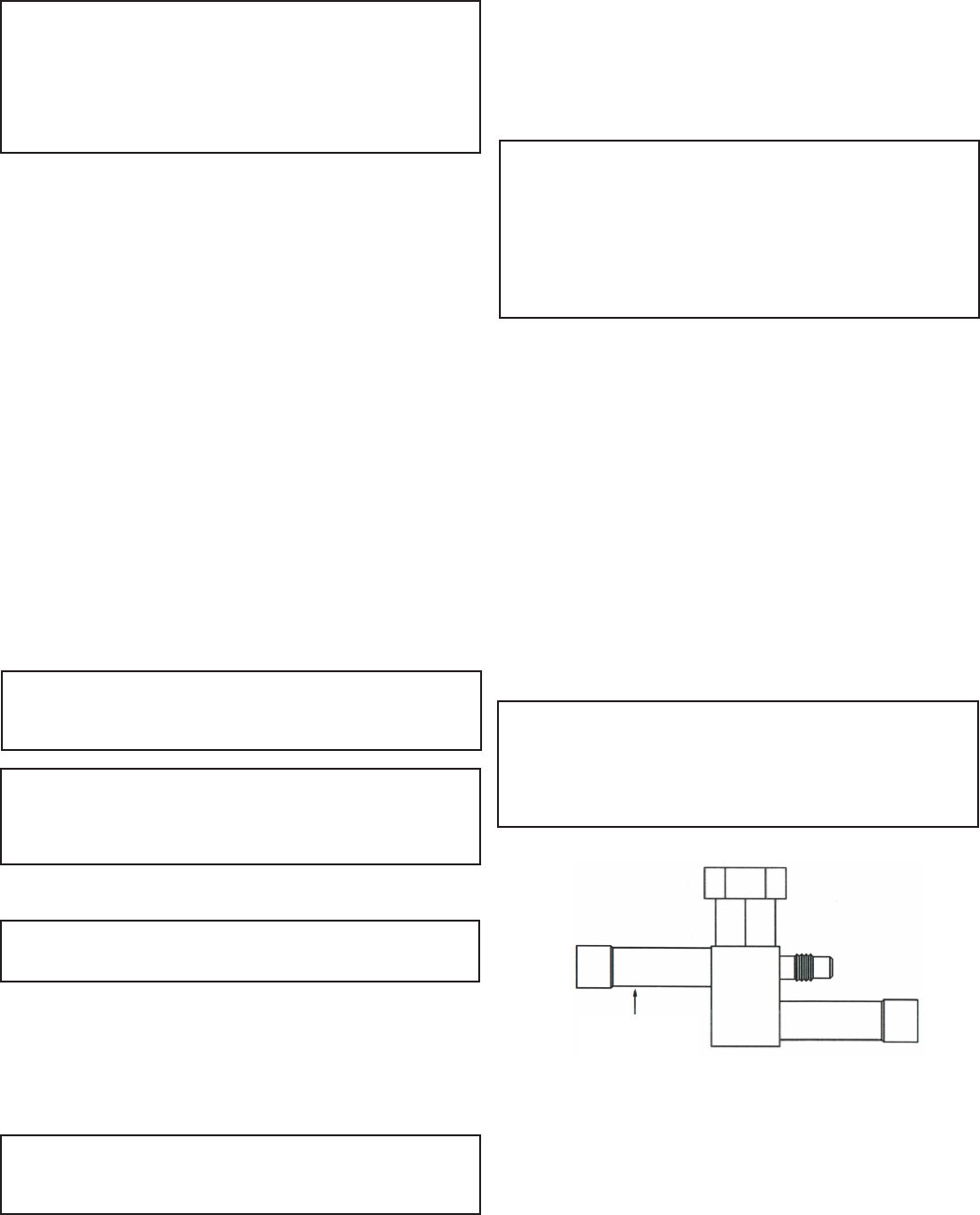
Figure 6. Dual Valve Piping Arrangement
A. Dual Valve System
The system employs an ORI (open on rise of inlet pressure) valve and an ORD
( open on rise of dierential pressure) valve. The high pressure discharge gas
is introduced above the liquid in the receiver tank. The receiver discharge is
regulated by the ORI valve.
The discharge pressure of the ORI valve must be adjusted to regulate the
unit for proper operating conditions. Adjust the ORI valve shown on the
following diagram to maintain a discharge pressure of 150 PSIG on medium
temperature systems and 100 PSIG on low temperature systems, see Figure 6.
Table 1. Ambient Fan Cycle Thermostat Settings
Models
Design Thermostat Settings
T.D. T1 T2 T3
30 40
2-fan units: 25 45
20 50
4-fan units: 15 55
30 40 30
3-fan units: 25 45 35
20 50 40
6-fan units: 15 55 45
30 40 30 20
8-fan units: 25 45 35 25
20 50 40 30
15 55 45 35
NOTE: Cycle pairs of fans on double wide units.
Operation and Adjustment
Condensing units with dual valves require sucient charge to partially ood
the condenser during low ambient conditions.
Valve adjustment should be made with gauges connected to the discharge
port of the compressor. Adjustments should be made during mild or
low ambient conditions. Turning the valve stem “clockwise” on the ORI
valve will increase the discharge pressure, while turning the valve stem
“counterclockwise” will decrease the discharge pressure.
If adjustments are made during warm ambient conditions, it may not be
possible to adjust the regulator valve as low as desired. Readjustment may
be necessary once cooler conditions prevail.
C. Ambient Fan Cycle Control
This is an automatic winter control method which will maintain a
condensing pressure within reasonable limits by cycling fan motors
in response to outside air temperature. The thermostat(s) should be
eld adjusted to shut o the fan when the condensing temperature is
reduced to approximately 70
˚
F. Table 1 lists approximate settings for
several system T.D.’s. These settings are approximate as they do not
take into account variations in load.
Head Pressure Control
Several types of head pressure control systems are available on condensing
units:
A. Dual Valve System. (See section on operation and adjustment.)
B. Single Valve System. (No adjustments possible for standard non-
adjustable version, See section on operation and adjustment of
adjustable version.)
C. Ambient Fan Cycle Control. (See section on operation
and adjustment.)
D. Variable Speed Fan Control
D. Variable Speed Fan Control
Variable speed fan controls must be set to maintain a discharge pressure
of 145 PSIG on medium temperature systems and 100 PSIG or 145 PSIG
depending on the model on low temperature systems.
Units using the Orbus Controller includes jumpers that can be set in the
eld as required. More information on the Variable Speed Motor with Orbus
Controller can be found in the subsequent pages of this document.
For other variable speed controllers, consult control manufacturer
information for details on how to set discharge pressure as required.
150 PSIG
B. Single Valve System
The standard valve used on Medium Temperature Refrigeration systems
controls the head pressure at approximately 145 PSIG. There is no
adjustment for this valve. On Low Temperature Refrigeration systems the
valve controls pressure at approximately 100 PSIG or 145 PSIG depending
on the model. For energy eciency, the 100 PSIG valve is sometimes used
on Medium Temperature Refrigeration systems.
At condensing pressures above the valve setting, ow enters Port C and
leaves Port R. When the condensing pressure falls below the valve setting,
the valve modulates to permit discharge gas to enter Port D. Metering
discharge gas into the refrigerant ow leaving the condenser produces a
higher pressure at the condenser outlet, reduces the ow, and causes the
level of liquid refrigerant to rise in the condenser. This “ooding” of the
condenser with liquid refrigerant reduces the available condensing surface,
holding the condensing pressure at the valve setting.
An adjustable single valve is an available option for some systems. These
valves are pre-set for the same pressures as the non-adjustable versions.

7
Polyol Ester Lubricants
Hygroscopicity
Since moisture levels greater than 100 ppm will results in system corrosion
and ultimate failure, it is imperative that compressors, components,
containers and the entire system be kept sealed as much as possible.
Lubricants will be packaged in specially designed, sealed containers. After
opening, all the lubricant in a container should be used at once since it will
readily absorb moisture if left exposed to the ambient. Any unused lubricant
should be properly disposed of. Similarly, work on systems and compressors
must be carried out with the open time as short as possible. Leaving the
system or compressor open during breaks or overnight MUST BE AVOIDED!
Color
As received, the POE lubricant will be clear or straw colored. After use, it may
acquire a darker color. This does not indicate a problem as the darker color
merely reects the activity of the lubricant's protective additive.
Oil Level
During Copeland's testing of Polyol ester oil, it was found that this lubricant
exhibits a greater tendency to introduce oil into the cylinder during ooded
start conditions. If allowed to continue, this condition will cause mechanical
failure of the compressor.
A crankcase heater is required with condensing units and it must be turned
on several hours before start-up.
Oil level must not exceed 1/4 sight glass.
Polyol Ester Lubricants
The preferred POE 32 is due to unique additives included in this lubricant.
POE’s must be used if HFC refrigerants are used in the system. They are
also acceptable for use with any of the traditional refrigerants or interim
blends and are compatible with mineral oils.
Phase Loss Monitor
When phase sequence is correct and full line voltage is present on all three
phases, the relay is energized as the normal condition indicator light glows.
If compressor fails to operate and the normal condition indicator light on the
phase monitor does not glow, then the supplied electrical current is not in phase
with the monitor. This problem is easily corrected by the following steps:
1. Turn power o at disconnect switch.
2. Swap any two of the three power input wires.
3. Turn power on. Indicator light should glow and compressor should start.
4. Observe motors for correct rotation.
8
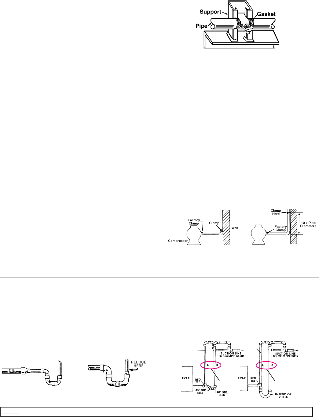
Figure 8. Example of Pipe Support
Figure 9. Condensing Unit / Compressor to Wall Support
Suction Lines
Horizontal suction lines should slope away from the evaporator toward
the compressor at the rate of 1/4 inch per 10 feet for good oil return. When
multiple evaporators are connected in series using a common suction line,
the branch suction lines must enter the top of the common suction line.
For dual or multiple evaporator systems, the branch lines to each evaporator
should be sized for the evaporator capacity. The main common line should
be sized for the total system capacity.
Suction lines that are outside of refrigerated space must be insulated.
Recommended Refrigerant Piping Practices
The system as supplied by Heatcraft Refrigeration Products, was thoroughly
cleaned and dehydrated at the factory. Foreign matter may enter the system
by way of the evaporator to condensing unit piping. Therefore, care must be
used during installation of the piping to prevent entrance of foreign matter.
Install all refrigeration system components in accordance with applicable local
and national codes and in conformance with good practice required for the
proper operation of the system.
The refrigerant pipe size should be selected from the Line Sizing Tables. The
interconnecting pipe size is not necessarily the same size as the stub-out on
the condensing unit or the evaporator.
The following procedures should be followed:
a) Do not leave dehydrated compressors or lter-driers on condensing units
open to the atmosphere any longer than is absolutely necessary.
b) Use only refrigeration grade copper tubing, properly sealed against
contamination.
c) Suction lines should slope 1/4" per 10 feet towards the compressor.
d) Suitable P-type oil traps should be located at the base of each suction
riser to enhance oil return to the compressor.
e) For desired method of superheat measurement, a pressure tap should be
installed in each evaporator suction line in the proximity of the expansion
valve bulb.
f) When brazing refrigerant lines, an inert gas should be passed
through the line at low pressure to prevent scaling and oxidation
inside the tubing. Dry nitrogen is preferred.
g) Use only a suitable silver solder alloy on suction and liquid lines.
h) Limit the soldering paste or ux to the minimum required to prevent
contamination of the solder joint internally. Flux only the male portion of
the connection, never the female. After brazing, remove excess ux.
i) See line sizing tables for discharge and liquid drain line sizes for remote
condenser connections.
j) If isolation valves are installed at the evaporator, full port ball valves
should be used.
Refrigerant Pipe Support
1. Normally, any straight run of tubing must be supported in at least two
locations near each end of the run. Long runs require additional
supports. The refrigerant lines should be supported and fastened
properly. As a guide, 3/8 to 7/8 should be supported every 5 feet; 1-1/8
and 1-3/8 every 7 feet; and 1-5/8 and 2-1/8 every 9 to 10 feet.
See Figure 10
2. When changing directions in a run of tubing, no corner should be left
unsupported. Supports should be placed a maximum of 2 feet in each
direction from the corner. See Figure 11
3. Piping attached to a vibrating object (such as a compressor or
compressor base) must be supported in such a manner that will not
restrict the movement of the vibrating object. Rigid mounting will
fatigue the copper tubing.
4. Do not use short radius ells. Short radius elbows have points of excessive
stress concentration and are subject to breakage at these points.
5. Thoroughly inspect all piping after the equipment is in operation and
add supports wherever line vibration is signicantly greater than most
of the other piping. Extra supports are relatively inexpensive as
compared to refrigerant loss.
Figure 10. Suction P-Traps
Suction Line Risers
Prefabricated wrought copper traps are available, or a trap can be made
by using two street ells and one regular ell. The suction trap must be the
same size as the suction line. For long vertical risers, additional traps may
be necessary. Generally, one trap is recommended for each length of pipe
(approximately 20 feet) to insure proper oil movement. See Figure 9 and
Figure 11 for methods of constructing proper suction line P-traps.
NOTE:
A suction line trap must be installed at the point where piping changes the direction of refrigerant ow from any horizontal run to an upward vertical run.
Figure 11. Double Suction Riser Construction
Slope 1/4"
per 10 ft.
toward
compressor
"Incorrect"
"Correct"
"Incorrect"
"Correct"
Sized for
Minimum
Load
Sized for
Full Load
Sized for
Minimum
Load
Sized for
Full Load
METHOD A
METHOD B
Refrigerant Piping
Install all refrigerant components in accordance with applicable local and national
codes and in accordance with good practice for proper system operation. The
thermostatic expansion valve must be the externally equalized type. It can be
mounted inside the unit end compartment. Mount the expansion valve bulb
on a horizontal run of suction line as close as possible to the suction header. Use
the clamps provided with the valve to fasten the bulb securely so there is a tight
line-to-line contact between the bulb and the suction line. Suction and hot gas
connections are made on the outside of the unit.
Suction lines should be sloped towards the compressor at the rate of one (1) inch
per ten (10) feet for good oil return. Vertical risers of more than four (4) feet should
be trapped at the bottom with a P-trap. If a P-trap is used, the expansion valve
bulb should be installed between the unit and the trap.
9
Liquid Lines
Liquid lines should be sized for a minimum pressure drop to prevent
“ashing”. Flashing in the liquid lines would create additional pressure drop
and poor expansion valve operation. If a system requires long liquid lines
from the receiver to the evaporator or if the liquid has to rise vertically
upward any distance, the losses should be calculated to determine whether
or not a heat exchanger is required. The use of a suction to liquid heat
exchanger may be used to subcool the liquid to prevent ashing. This
method of subcooling will normally provide no more than 20
˚
F subcooling
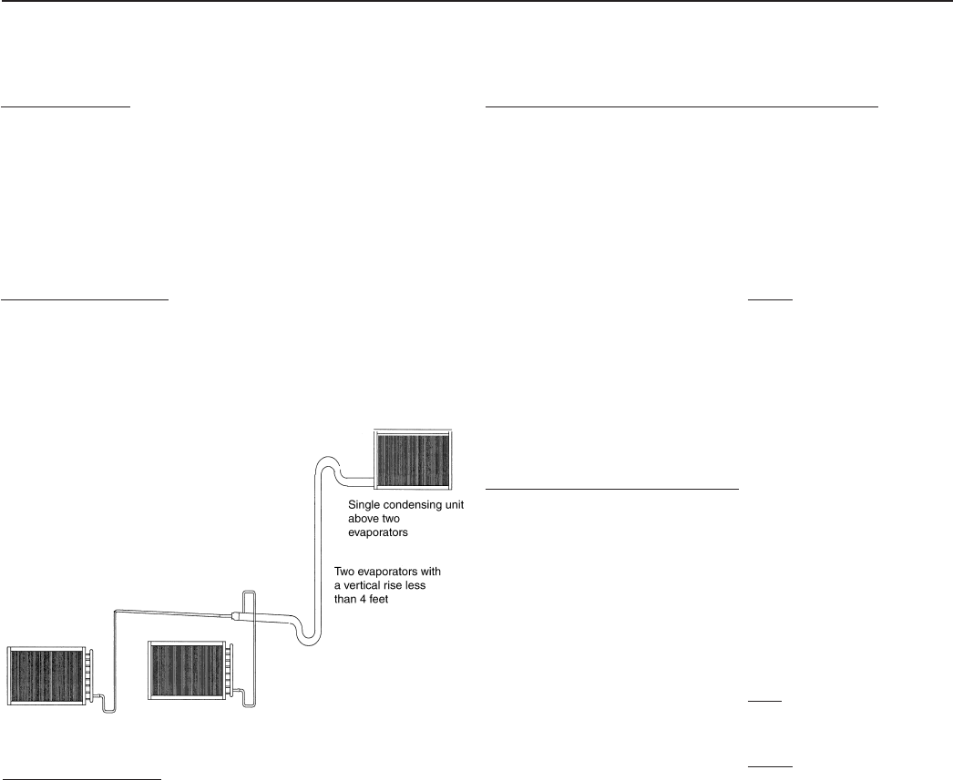
Pipe size example:
Given: -10°F Freezer with one system having (2) evaporators
• One condensing unit rated at 24,000 BTUH’s @ -20°F SST R404A
refrigerant.
• Two evaporators each rated at 12,000 BTUH’s @ 10°F TD.
• 100 feet of actual line run between condensing unit to rst evaporator
and 20 feet of actual line run between the rst evaporator and the
second evaporator (see gure below).
How to gure line sizes:
1. Determine equivalent line run = actual run + valves and tting
allowances.
2. Use Line Sizing Tables to size lines.
3. Note any special considerations.
Fittings in this system:
• (6) 90° elbows in main line plus a 90° turn through a tee.
• (5) addtional 90° elbows to rst evaporator.
• (4) additional 90° elbows to second evaporator.
Determine line size 1 (main line from condensing unit):
1. Main line from the condensing unit to be sized for the total capacity
(balance) of the whole system of 24,000 BTUH’s.
2. Refer to 24,000 @100 feet at -20°F SST R404A on the chart.
You will nd the suction line to be 1-3/8" and 1/2" liquid line.
3. For every 1-3/8" 90° elbow you must add 4 equivalent feet of pipe
and 2.5 equivalent feet of pipe for each 1-3/8" tee.
Therefore, total equivalent line run =
Actual line run 100 feet
+ (6) 1-3/8" elbows @ 4' 24 feet
+ (1) 1-3/8" tee @ 2.5' 2.5 feet
Total equivalent line run 126.5 feet
4. For 126.5 total equivalent feet, the suction line size should be
1-3/8" and the liquid line stays at 1/2" line.
Note: On Table 6, for 24,000 BTUH’s, the maximum suction riser is 1-1/8" to
insure proper oil return and pressure drop from the bottom p-trap to the top
p-trap.
Determine line size 2 (evaporators):
1. Line sizing to each evaporator is based on 12,000 BTUH’s and
equivalent run from condensing unit. First evaporator has an 105 ft.
run and the second evaporator has a 120 ft. run.
2. Line sizing table indicates 1-1/8" suction for the rst evaporator and
indicates 1-1/8" suction for the second evaporator.
3. Refer to Table 4. Each 1-1/8" 90° elbow adds 3 equivalent feet of pipe.
Each 90° turn through a 1-1/8" tee adds 6 equivalent feet.
4. Actual line run (evap 1) 105 feet
+ (5) 1-1/8" elbows @ 3' 15 feet
+ (1) 90° turn through tee @ 6' 6 feet
Total equivalent line run 126 feet
Actual line run (evap 2) 120 feet
+ (4) 1-1/8" elbows @ 3' 12 feet
Total equivalent line run 132 feet
5. Table 6 indicates 1-1/8" suction line and 3/8" liquid line from
main line to both evaporators.
Unit Cooler Piping
Evap. 1
Evap. 2
Evap. 2 Evap. 1
Line Size 2
Line Size 1
Figure 9. Condensing Unit / Compressor to Wall Support
Diagram 3
on high pressure systems. The amount of subcooling will depend on the
design and size of the heat exchanger and on the operating suction and
discharge pressures. An additional benet from the use of the suction to
liquid type heat exchanger is that it can help raise the superheat in the
suction line to prevent liquid return to the compressor via the suction line.
Generally, heat exchangers are not recommended on R-22 low temperature
systems. However, they have proved necessary on short, well insulated
suction line runs to provide superheat at the compressor.
10
Table 3. Pressure Loss of Liquid Refrigerants in Liquid Line Risers (Expressed in Pressure Drop, PSIG, and Subcooling Loss, ˚F)
Refrigerant
Liquid Line Rise in Feet
10' 15' 20' 25' 30' 40' 50' 75' 100'
PSIG ˚F PSIG ˚F PSIG ˚F PSIG ˚F PSIG ˚F PSIG ˚F PSIG ˚F PSIG ˚F PSIG ˚F
R-407A, R-407C, R-407F 4.3 1.4 6.4 2.0 8.5 2.7 10.6 3.4 12.8 4.1 17.0 5.4 21.3 6.8 31.9 10.1 42.5 13.5
R-448A, R-449A
4.3 1.1 6.5 1.7 8.7 2.3 10.9 2.8 13.0 3.4 17.4 4.5 21.7 5.6 32.6 8.3 43.5 10.9
R-507, R-404A
4.1 1.1 6.1 1.6 8.2 2.1 10.2 2.7 12.2 3.3 16.3 4.1 20.4 5.6 30.6 8.3 40.8 11.8
Based on 110˚F liquid temperature at bottom of riser.
Table 4. Equivalent Feet of Pipe Due to Valve and Fitting Friction
Copper Tube, O.D., Type “L” 1/2 5/8 7/8 1-1/8 1-3/8 1-5/8 2-1/8 2-5/8 3-1/8 3-5/8 4-1/8 5-1/8 6-1/8
Globe Valve (Open) 14 16 22 28 36 42 57 69 83 99 118 138 168
Angle Valve (Open) 7 9 12 15 18 21 28 34 42 49 57 70 83
90˚ Turn Through Tee 3 4 5 6 8 9 12 14 17 20 22 28 34
Tee (Straight Through) or Sweep Below .75 1 1.5 2 2.5 3 3.5 4 5 6 7 9 11
90˚ Elbow or Reducing Tee (Straight Through)
1 2 2 3 4 4 5 7 8 10 12 14 16
Table 2. Weight of Refrigerants in Copper Lines During Operation (Pounds per 100 lineal feet of type "L" tubing)
Line Size O.D.
(Inches)
Refrigerant Liquid Line Hot Gas Line
Suction Line at Suction Temperature
-40˚F -20˚F 0˚F +20˚F +40˚F
3/8
R-407A, R-407C, R-407F 3.8 0.25 0.02 0.03 0.04 0.06 0.09
R-448A, R-449A 3.6 0.24 0.02 0.03 0.04 0.06 0.09
R-404A, R-507A 3.4 0.27 0.02 0.04 0.06 0.08 0.12
1/2
R-407A, R-407C, R-407F 7.0 0.46 0.03 0.05 0.07 0.11 0.16
R-448A, R-449A 6.7 0.44 0.03 0.05 0.07 0.11 0.16
R-404A, R-507A 6.3 0.51 0.04 0.07 0.11 0.15 0.22
5/8
R-407A, R-407C, R-407F 11.2 0.74 0.05 0.08 0.12 0.18 0.26
R-448A, R-449A 10.8 0.71 0.05 0.08 0.12 0.18 0.26
R-404A, R-507A 10.2 0.82 0.07 0.11 0.17 0.25 0.35
7/8
R-407A, R-407C, R-407F 23.3 1.54 0.10 0.16 0.25 0.37 0.55
R-448A, R-449A 22.3 1.47 0.10 0.16 0.25 0.37 0.54
R-404A, R-507A 21.1 1.70 0.15 0.23 0.35 0.51 0.74
1-1/8
R-407A, R-407C, R-407F 39.7 2.62 0.16 0.27 0.42 0.64 0.93
R-448A, R-449A 38.1 2.51 0.17 0.27 0.42 0.64 0.92
R-404A, R-507A 36.1 2.89 0.25 0.39 0.60 0.88 1.25
1-3/8
R-407A, R-407C, R-407F 60.5 4.00 0.25 0.41 0.64 0.97 1.42
R-448A, R-449A 58.0 3.83 0.26 0.42 0.65 0.97 1.41
R-404A, R-507A 54.9 4.41 0.38 0.60 0.91 1.34 1.91
1-5/8
R-407A, R-407C, R-407F 85.7 5.66 0.35 0.58 0.91 1.37 2.01
R-448A, R-449A 82.1 5.42 0.36 0.59 0.92 1.37 1.99
R-404A, R-507A 77.7 6.24 0.54 0.85 1.29 1.89 2.71
2-1/8
R-407A, R-407C, R-407F 149 9.84 0.61 1.01 1.58 2.39 3.50
R-448A, R-449A 143 9.43 0.63 1.02 1.58 2.39 3.47
R-404A, R-507A 135 10.85 0.94 1.48 2.24 3.29 4.71
2-5/8
R-407A, R-407C, R-407F 230 15.18 0.95 1.55 2.44 3.68 5.39
R-448A, R-449A 220 14.54 0.97 1.58 2.46 3.68 5.35
R-404A, R-507A 209 16.73 1.45 2.28 3.45 5.07 7.26
3-1/8
R-407A, R-407C, R-407F 328 21.66 0.35 2.22 3.48 5.26 7.69
R-448A, R-449A 314 20.76 1.39 2.25 3.50 5.25 7.64
R-404A, R-507A 298 23.88 2.06 3.25 4.93 7.24 10.36
3-5/8
R-407A, R-407C, R-407F 444 29.30 1.83 3.00 4.71 7.11 10.41
R-448A, R-449A 425 28.07 1.87 3.05 4.74 7.10 10.33
R-404A, R-507A 403 32.30 2.79 4.40 6.67 9.79 14.01
4-1/8
R-407A, R-407C, R-407F 577 38.08 2.37 3.90 6.12 9.24 13.53
R-448A, R-449A 552 36.49 2.44 3.96 6.16 9.23 13.42
R-404A, R-507A 523 41.99 3.63 5.72 8.67 12.72 18.21
Line Sizing
The following Tables 5-8 indicate liquid lines and suction lines for all
condensing units for R-404A, R-507, R-407A/C/F, R-448A and R-449A
When determining the refrigerant line length, be sure to add an allowance
for ttings. See Table 4. Total equivalent length of refrigerant lines is the sum
of the actual linear footage and the allowance for ttings.
11
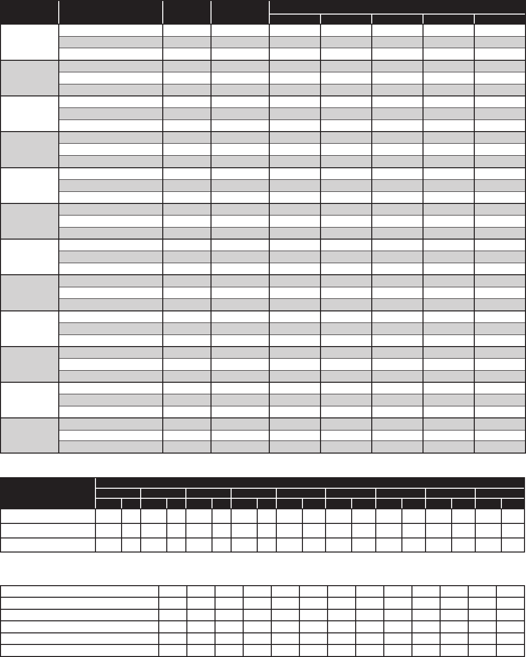
Table 5. Recommended Remote Condenser Line Sizes
Net Evaporator
Capacity
Total Equiv.
Length
R-407A/C/F, R-448A & R-449A R-507 & R-404A
Discharge Line (O.D.)
Liquid Line Cond. to
Receiver (O.D.)
Discharge Line (O.D.)
Liquid Line Cond. to
Receiver (O.D.)
3,000
50 3/8 3/8 3/8 3/8
100 3/8 3/8 3/8 3/8
6,000
50 3/8 3/8 1/2 3/8
100 1/2 3/8 1/2 3/8
9,000
50 1/2 3/8 1/2 3/8
100 1/2 3/8 1/2 3/8
12,000
50 1/2 3/8 1/2 3/8
100 5/8 3/8 5/8 1/2
18,000
50 5/8 3/8 5/8 1/2
100 5/8 3/8 7/8 1/2
24,000
50 5/8 3/8 5/8 1/2
100 7/8 1/2 7/8 5/8
36,000
50 7/8 1/2 7/8 5/8
100 7/8 5/8 7/8 7/8
48,000
50 7/8 5/8 7/8 5/8
100 7/8 7/8 1-1/8 7/8
60,000
50 7/8 5/8 7/8 7/8
100 1-1/8 7/8 1-1/8 7/8
72,000
50 7/8 7/8 1-1/8 7/8
100 1-1/8 7/8 1-1/8 1-1/8
90,000
50 1-1/8 7/8 1-1/8 7/8
100 1-1/8 7/8 1-1/8 1-1/8
120,000
50 1-1/8 7/8 1-1/8 1-1/8
100 1-3/8 1-1/8 1-3/8 1-3/8
180,000
50 1-3/8 1-1/8 1-3/8 1-3/8
100 1-5/8 1-3/8 1-5/8 1-5/8
240,000
50 1-3/8 1-3/8 1-5/8 1-3/8
100 1-5/8 1-3/8 2-1/8 1-5/8
300,000
50 1-5/8 1-3/8 1-5/8 1-5/8
100 2-1/8 1-5/8 2-1/8 2-1/8
360,000
50 1-5/8 1-5/8 2-1/8 1-5/8
100 2-1/8 2-1/8 2-1/8 2-1/8
480,000
50 2-1/8 1-5/8 2-1/8 2-1/8
100 2-1/8 2-1/8 2-1/8 2-5/8
600,000
50 2-1/8 2-1/8 2-1/8 2-1/8
100 2-5/8 2-5/8 2-5/8 2-5/8
720,000
50 2-1/8 2-1/8 2-1/8 2-5/8
100 2-5/8 2-5/8 2-5/8 3-1/8
840,000
50 2-1/8 2-1/8 2-5/8 2-5/8
100 2-5/8 2-5/8 2-5/8 3-1/8
960,000
50 2-5/8 2-5/8 2-5/8 2-5/8
100 2-5/8 3-1/8 3-1/8 3-5/8
1,080,000
50 2-5/8 2-5/8 2-5/8 3-1/8
100 3-1/8 3-1/8 3-1/8 3-5/8
1,200,000
50 2-5/8 2-5/8 2-5/8 3-1/8
100 3-1/8 3-1/8 3-5/8 4-1/8
1,440,000
50 2-5/8 3-1/8 3-1/8 3-5/8
100 3-1/8 3-5/8 3-5/8 4-1/8
1,680,000
50 3-1/8 3-1/8 3-1/8 3-5/8
100 3-5/8 3-5/8 3-5/8 4-1/8
12
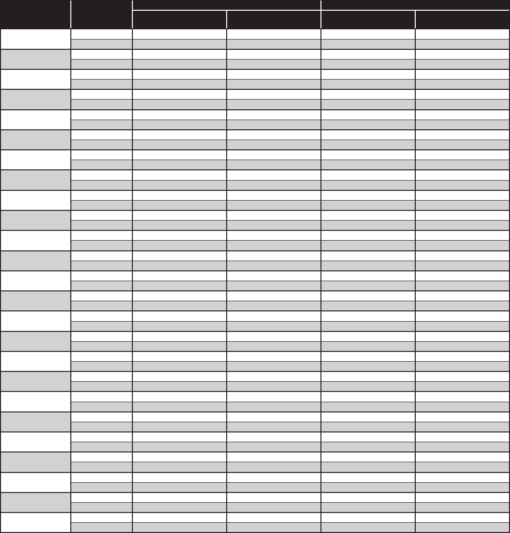
* NOTES:
1. Sizes that are highlighted indicate maximum suction line sizes that should be used for risers. Riser size should not exceed horizontal size.
Properly placed suction traps must also be used for adequate oil return.
All sizes shown are for O.D. Type L copper tubing.
2. Suction line sizes selected at pressure drop equivalent to 2˚F. Reduce estimate of system capacity accordingly.
3. Recommended liquid line size may increase with reverse cycle hot gas systems.
4. If system load drops below 40% of design, consideration to installing double suction risers should be made.
Table 6. Recommended Line Sizes for R-404A, R-507*
Capacity
BTUH
Suction Line Size Maximum Suction Line Riser Size
Suction Temperature
R-404A /507
Suction Temperature
+40˚F
Equivalent Lengths
+20˚F
Equivalent Lengths
+10˚F
Equivalent Lengths
25' 50' 100' 150' 25' 50' 100' 150' 25' 50' 100' 150' +40 +20 +10 -10 -20 -30 -40
1,000 3/8 3/8 3/8 3/8 3/8 3/8 3/8 3/8 3/8 3/8 3/8 3/8
3/8 3/8 3/8 3/8 1/2 1/2 1/2
3,000 3/8 3/8 1/2 1/2 3/8 3/8 1/2 1/2 3/8 1/2 1/2 5/8
3/8 3/8 1/2 1/2 1/2 1/2 1/2
4,000 3/8 1/2 1/2 1/2 3/8 1/2 1/2 5/8 1/2 1/2 5/8 5/8
3/8 1/2 1/2 1/2 5/8 5/8 5/8
6,000 1/2 1/2 1/2 5/8 1/2 1/2 5/8 7/8 1/2 1/2 5/8 7/8
1/2 1/2 1/2 1/2 5/8 5/8 7/8
9,000 1/2 5/8 5/8 5/8 5/8 5/8 7/8 7/8 5/8 5/8 7/8 7/8
1/2 5/8 5/8 7/8 7/8 7/8 7/8
12,000 1/2 5/8 7/8 7/8 5/8 7/8 7/8 7/8 5/8 7/8 7/8 7/8
1/2 7/8 7/8 7/8 7/8 1-1/8 1-1/8
15,000 5/8 5/8 7/8 7/8 5/8 7/8 7/8 7/8 7/8 7/8 7/8 1-1/8
5/8 7/8 7/8 7/8 7/8 1-1/8 1-1/8
18,000 5/8 7/8 7/8 7/8 7/8 7/8 7/8 1-1/8 7/8 7/8 1-1/8 1-1/8
5/8 7/8 7/8 1-1/8 1-1/8 1-1/8 1-1/8
24,000 5/8 7/8 7/8 7/8 7/8 7/8 1-1/8 1-1/8 7/8 1-1/8 1-1/8 1-1/8
5/8 1-1/8 1-1/8 1-1/8 1-1/8 1-3/8 1-3/8
30,000 7/8 7/8 7/8 1-1/8 7/8 7/8 1-1/8 1-1/8 7/8 1-1/8 1-1/8 1-3/8
7/8 1-1/8 1-1/8 1-1/8 1-1/8 1-3/8 1-3/8
36,000 7/8 7/8 1-1/8 1-1/8 7/8 1-1/8 1-1/8 1-3/8 1-1/8 1-1/8 1-3/8 1-3/8
7/8 1-1/8 1-1/8 1-1/8 1-1/8 1-3/8 1-3/8
42,000 7/8 7/8 1-1/8 1-1/8 1-1/8 1-1/8 1-3/8 1-3/8 1-1/8 1-1/8 1-3/8 1-3/8
7/8 1-3/8 1-3/8 1-3/8 1-3/8 1-5/8 1-5/8
48,000 7/8 1-1/8 1-1/8 1-1/8 1-1/8 1-1/8 1-3/8 1-3/8 1-1/8 1-1/8 1-3/8 1-5/8
7/8 1-3/8 1-3/8 1-3/8 1-3/8 1-5/8 1-5/8
54,000 7/8 1-1/8 1-1/8 1-3/8 1-1/8 1-1/8 1-3/8 1-3/8 1-1/8 1-3/8 1-3/8 1-5/8
1-1/8 1-3/8 1-3/8 1-3/8 1-3/8 1-5/8 1-5/8
60,000 7/8 1-1/8 1-1/8 1-3/8 1-1/8 1-1/8 1-3/8 1-5/8 1-1/8 1-3/8 1-5/8 1-5/8
1-1/8 1-5/8 1-5/8 1-5/8 1-5/8 1-5/8 1-5/8
66,000 1-1/8 1-1/8 1-3/8 1-3/8 1-1/8 1-3/8 1-3/8 1-5/8 1-1/8 1-3/8 1-5/8 1-5/8
1-1/8 1-5/8 1-5/8 1-5/8 1-5/8 1-5/8 1-5/8
72,000 1-1/8 1-1/8 1-3/8 1-3/8 1-1/8 1-3/8 1-5/8 1-5/8 1-1/8 1-3/8 1-5/8 1-5/8
1-1/8 1-5/8 1-5/8 1-5/8 1-5/8 1-5/8 1-5/8
78,000 1-1/8 1-1/8 1-3/8 1-3/8 1-1/8 1-3/8 1-5/8 1-5/8 1-3/8 1-3/8 1-5/8 1-5/8
1-1/8 1-5/8 1-5/8 1-5/8 1-5/8 1-5/8 1-5/8
84,000 1-1/8 1-1/8 1-3/8 1-3/8 1-1/8 1-3/8 1-5/8 1-5/8 1-3/8 1-3/8 1-5/8 2-1/8
1-3/8 1-5/8 1-5/8 1-5/8 1-5/8 2-1/8 1-5/8
90,000 1-1/8 1-3/8 1-3/8 1-5/8 1-3/8 1-3/8 1-5/8 2-1/8 1-3/8 1-5/8 1-5/8 2-1/8
1-3/8 1-5/8 1-5/8 1-5/8 2-1/8 2-1/8 2-1/8
120,000
1-1/8 1-3/8 1-5/8 1-5/8 1-3/8 1-5/8 2-1/8 2-1/8 1-3/8 1-5/8 2-1/8 2-1/8
1-5/8 2-1/8 2-1/8 2-1/8 2-1/8 2-1/8 2-1/8
150,000
1-3/8 1-3/8 1-5/8 2-1/8 1-5/8 1-5/8 2-1/8 2-1/8 1-5/8 2-1/8 2-1/8 2-1/8
1-5/8 2-1/8 2-1/8 2-1/8 2-1/8 2-1/8 2-5/8
180,000
1-3/8 1-5/8 2-1/8 2-1/8 1-5/8 2-1/8 2-1/8 2-1/8 1-5/8 2-1/8 2-1/8 2-5/8
1-5/8 2-1/8 2-1/8 2-5/8 2-5/8 2-5/8 2-5/8
210,000
1-3/8 1-5/8 2-1/8 2-1/8 1-5/8 2-1/8 2-1/8 2-5/8 2-1/8 2-1/8 2-5/8 2-5/8
2-1/8 2-5/8 2-5/8 2-5/8 2-5/8 2-5/8 3-1/8
240,000
1-5/8 1-5/8 2-1/8 2-1/8 1-5/8 2-1/8 2-1/8 2-5/8 2-1/8 2-1/8 2-5/8 2-5/8
2-1/8 2-5/8 2-5/8 2-5/8 2-5/8 3-1/8 3-1/8
300,000
1-5/8 2-1/8 2-1/8 2-5/8 2-1/8 2-1/8 2-5/8 2-5/8 2-1/8 2-5/8 2-5/8 3-1/8
2-1/8 2-5/8 2-5/8 2-5/8 2-5/8 3-5/8 3-5/8
360,000
2-1/8 2-1/8 2-5/8 2-5/8 2-1/8 2-1/8 2-5/8 3-1/8 2-1/8 2-5/8 2-5/8 3-1/8
2-5/8 2-5/8 3-1/8 3-5/8 3-5/8 3-5/8 4-1/8
480,000
2-1/8 2-1/8 2-5/8 2-5/8 2-1/8 2-5/8 3-1/8 3-1/8 2-5/8 2-5/8 2-5/8 3-5/8
2-5/8 3-1/8 3-5/8 3-5/8 3-5/8 3-5/8 4-1/8
600,000
2-1/8 2-5/8 2-5/8 3-1/8 2-5/8 2-5/8 3-1/8 3-5/8 2-5/8 2-5/8 3-1/8 3-5/8
3-1/8 3-5/8 3-5/8 3-5/8 3-5/8 4-1/8 4-1/8
13
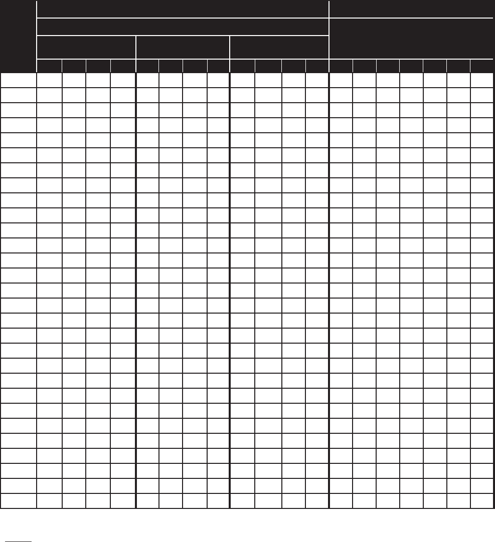
Suction Line Size Liquid Line Size
Capacity
BTUH
Suction Temperature
Receiver to Expansion
Valve Equivalent Lengths
-10 ˚F
Equivalent Lengths
-20˚F
Equivalent Lengths
-30˚F
Equivalent Lengths
-40˚F
Equivalent Lengths
25' 50' 100' 150' 25' 50' 100' 150' 25' 50' 100' 150' 25' 50' 100' 150' 25' 50' 100' 150'
1,000
3/8 3/8 1/2 1/2 3/8 3/8 1/2 1/2 3/8 3/8 1/2 1/2 3/8 1/2 1/2 5/8 3/8 3/8 3/8 3/8
3,000
1/2 1/2 5/8 5/8 1/2 1/2 5/8 7/8 1/2 1/2 5/8 7/8 1/2 1/2 5/8 7/8 3/8 3/8 3/8 3/8
4,000
1/2 5/8 5/8 7/8 1/2 5/8 7/8 7/8 5/8 5/8 7/8 7/8 1/2 5/8 7/8 7/8 3/8 3/8 3/8 3/8
6,000
1/2 5/8 7/8 7/8 5/8 5/8 7/8 7/8 5/8 5/8 7/8 7/8 5/8 5/8 ⁄ 7/8 3/8 3/8 3/8 3/8
9,000
5/8 7/8 7/8 7/8 5/8 7/8 7/8 1-1/8 5/8 7/8 7/8 1-1/8 5/8 7/8 7/8 1-1/8 3/8 3/8 3/8 3/8
12,000
7/8 7/8 7/8 1-1/8 7/8 7/8 1-1/8 1-1/8 7/8 7/8 1-1/8 1-1/8 7/8 7/8 1-1/8 1-1/8 3/8 3/8 3/8 3/8
15,000
7/8 7/8 1-1/8 1-1/8 7/8 7/8 1-1/8 1-1/8 7/8 7/8 1-1/8 1-1/8 7/8 7/8 1-1/8 1-1/8 3/8 3/8 3/8 1/2
18,000
7/8 7/8 1-1/8 1-1/8 7/8 1-1/8 1-1/8 1-3/8 7/8 1-1/8 1-1/8 1-3/8 7/8 1-1/8 1-1/8 1-3/8 3/8 3/8 1/2 1/2
24,000
7/8 1-1/8 1-1/8 1-3/8 1-1/8 1-1/8 1-3/8 1-3/8 1-1/8 1-1/8 1-3/8 1-3/8 1-1/8 1-1/8 1-3/8 1-3/8 3/8 3/8 1/2 1/2
30,000
1-1/8 1-1/8 1-3/8 1-3/8 1-1/8 1-1/8 1-3/8 1-3/8 1-1/8 1-1/8 1-3/8 1-3/8 1-1/8 1-1/8 1-3/8 1-3/8 3/8 1/2 1/2 1/2
36,000
1-1/8 1-1/8 1-3/8 1-3/8 1-1/8 1-1/8 1-3/8 1-3/8 1-1/8 1-3/8 1-3/8 1-3/8 1-1/8 1-3/8 1-3/8 1-5/8 1/2 1/2 1/2 1/2
42,000
1-1/8 1-3/8 1-3/8 1-5/8 1-1/8 1-3/8 1-5/8 1-5/8 1-1/8 1-3/8 1-3/8 1-5/8 1-1/8 1-3/8 1-3/8 1-5/8 1/2 1/2 1/2 5/8
48,000
1-1/8 1-3/8 1-3/8 1-5/8 1-1/8 1-3/8 1-5/8 1-5/8 1-1/8 1-3/8 1-3/8 1-5/8 1-1/8 1-3/8 1-3/8 1-5/8 1/2 1/2 5/8 5/8
54,000
1-3/8 1-3/8 1-5/8 1-5/8 1-3/8 1-3/8 1-5/8 1-5/8 1-3/8 1-3/8 1-5/8 1-5/8 1-3/8 1-3/8 1-5/8 1-5/8 1/2 1/2 5/8 5/8
60,000
1-3/8 1-3/8 1-5/8 1-5/8 1-3/8 1-3/8 1-5/8 1-5/8 1-3/8 1-3/8 1-5/8 1-5/8 1-3/8 1-3/8 1-5/8 1-5/8 1/2 1/2 5/8 5/8
66,000
1-3/8 1-5/8 1-5/8 1-5/8 1-3/8 1-5/8 1-5/8 1-5/8 1-3/8 1-5/8 1-5/8 1-5/8 1-3/8 1-5/8 1-5/8 1-5/8 1/2 1/2 5/8 5/8
72,000
1-3/8 1-5/8 1-5/8 1-5/8 1-3/8 1-5/8 1-5/8 1-5/8 1-3/8 1-5/8 1-5/8 1-5/8 1-3/8 1-5/8 1-5/8 1-5/8 1/2 5/8 5/8 5/8
78,000
1-3/8 1-5/8 1-5/8 1-5/8 1-5/8 1-5/8 1-5/8 2-1/8 1-5/8 1-5/8 1-5/8 2-1/8 1-5/8 1-5/8 1-5/8 2-1/8 5/8 5/8 5/8 5/8
84,000
1-3/8 1-5/8 1-5/8 2-1/8 1-5/8 1-5/8 2-1/8 2-1/8 1-5/8 1-5/8 2-1/8 2-1/8 1-5/8 1-5/8 2-1/8 2-1/8 5/8 5/8 5/8 7/8
90,000
1-5/8 1-5/8 2-1/8 2-1/8 1-5/8 1-5/8 2-1/8 2-1/8 1-5/8 2-1/8 2-1/8 2-1/8 1-5/8 1-5/8 2-1/8 2-1/8 5/8 5/8 7/8 7/8
120,000
1-5/8 2-1/8 2-1/8 2-5/8 1-5/8 2-1/8 2-1/8 2-5/8 1-5/8 2-1/8 2-1/8 2-5/8 1-5/8 2-1/8 2-1/8 2-5/8 5/8 5/8 7/8 7/8
150,000
2-1/8 2-1/8 2-5/8 2-5/8 2-1/8 2-1/8 2-5/8 2-5/8 2-1/8 2-1/8 2-5/8 2-5/8 2-1/8 2-1/8 2-5/8 2-5/8 5/8 7/8 7/8 7/8
180,000
2-1/8 2-1/8 2-5/8 2-5/8 2-1/8 2-1/8 2-5/8 2-5/8 2-1/8 2-1/8 2-5/8 2-5/8 2-1/8 2-1/8 2-5/8 2-5/8 7/8 7/8 7/8 1-1/8
210,000
2-1/8 2-1/8 2-5/8 3-1/8 2-1/8 2-5/8 2-5/8 3-1/8 2-1/8 2-5/8 2-5/8 3-1/8 2-1/8 2-5/8 2-5/8 3-1/8 7/8 7/8 1-1/8 1-1/8
240,000
2-1/8 2-5/8 2-5/8 3-1/8 2-1/8 2-5/8 2-5/8 3-1/8 2-5/8 2-5/8 3-1/8 3-1/8 2-5/8 2-5/8 3-1/8 3-1/8 7/8 7/8 1-1/8 1-1/8
300,000
2-5/8 2-5/8 3-1/8 3-1/8 2-5/8 2-5/8 3-1/8 3-5/8 2-5/8 2-5/8 3-1/8 3-5/8 2-5/8 2-5/8 3-5/8 3-5/8 7/8 1-1/8 1-1/8 1-3/8
360,000
2-5/8 2-5/8 3-1/8 3-5/8 2-5/8 2-5/8 3-5/8 3-5/8 2-5/8 3-1/8 3-5/8 3-5/8 2-5/8 3-1/8 3-5/8 4-1/8 1-1/8 1-1/8 1-3/8 1-3/8
480,000
2-5/8 3-1/8 3-5/8 3-5/8 2-5/8 3-1/8 3-5/8 3-5/8 3-1/8 3-5/8 4-1/8 4-1/8 3-1/8 3-5/8 4-1/8 4-1/8 1-1/8 1-1/8 1-3/8 1-5/8
600,000
3-1/8 3-1/8 3-5/8 4-1/8 3-1/8 3-1/8 3-5/8 3-5/8 3-1/8 3-5/8 4-1/8 4-1/8 3-1/8 3-5/8 4-1/8 4-1/8 1-1/8 1-3/8 1-5/8 1-5/8
Table 6a. Recommended Line Sizes for R-404A, R-507* (cont.)
* NOTES:
1. Sizes that are highlighted indicate maximum suction line sizes that should be used for risers. Riser size should not exceed horizontal size.
Properly placed suction traps must also be used for adequate oil return.
All sizes shown are for O.D. Type L copper tubing.
2. Suction line sizes selected at pressure drop equivalent to 2˚F. Reduce estimate of system capacity accordingly.
3. Recommended liquid line size may increase with reverse cycle hot gas systems.
4. If system load drops below 40% of design, consideration to installing double suction risers should be made.
14
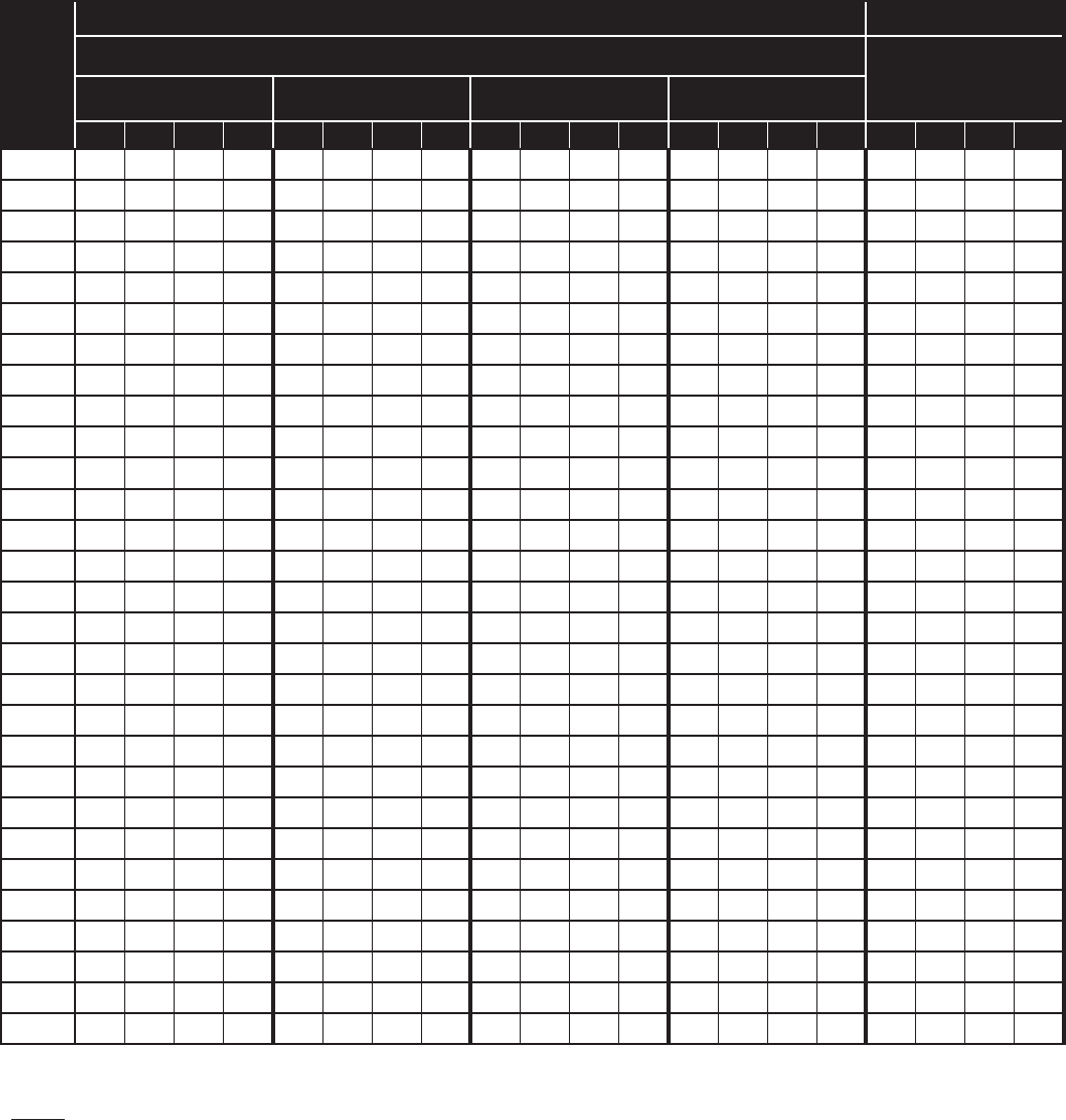
* NOTES:
1. Sizes that are highlighted indicate maximum suction line sizes that should be used for risers. Riser size should not exceed horizontal size.
Properly placed suction traps must also be used for adequate oil return.
All sizes shown are for O.D. Type L copper tubing.
2. Suction line sizes selected at pressure drop equivalent to 2˚F. Reduce estimate of system capacity accordingly.
3. Recommended liquid line size may increase with reverse cycle hot gas systems.
4. If system load drops below 40% of design, consideration to installing double suction risers should be made.
Suction Line Size
Maximum Suction Line Riser Size
Capacity
BTUH
Suction Temperature
R-407A/C/F
Suction Temperature
+40˚F
Equivalent Lengths
+20˚F
Equivalent Lengths
+10˚F
Equivalent Lengths
25' 50' 100' 150' 25' 50' 100' 150' 25' 50' 100' 150'
+40 +20 +10 -10 -20 -30 -40
1,000
3/8 3/8 3/8 3/8 3/8 3/8 3/8 3/8
3/8 3/8 3/8 3/8
3/8 3/8 3/8 3/8 3/8 3/8 3/8
3,000
3/8 3/8 3/8 1/2 3/8 3/8 1/2 1/2
1/2 1/2 1/2 5/8
3/8 3/8 1/2 1/2 1/2 5/8 5/8
4,000
3/8 3/8 1/2 1/2 3/8 1/2 1/2 5/8
1/2 5/8 5/8 5/8
1/2 1/2 1/2 1/2 5/8 5/8 5/8
6,000
3/8 1/2 1/2 5/8 1/2 1/2 5/8 5/8
1/2 5/8 7/8 7/8
1/2 1/2 1/2 5/8 5/8 7/8 7/8
9,000
1/2 1/2 5/8 5/8 1/2 5/8 7/8 7/8
5/8 7/8 7/8 7/8
5/8 5/8 5/8 5/8 7/8 7/8 1-1/8
12,000
1/2 5/8 7/8 7/8 5/8 5/8 7/8 7/8
5/8 7/8 7/8 7/8
5/8 7/8 5/8 7/8 7/8 1-1/8 1-3/8
15,000
5/8 5/8 7/8 7/8 5/8 7/8 7/8 7/8
7/8 7/8 7/8 1-1/8
7/8 7/8 7/8 7/8 1-1/8 1-3/8 1-3/8
18,000
5/8 7/8 7/8 7/8 5/8 7/8 7/8 7/8
7/8 7/8 1-1/8 1-1/8
7/8 7/8 7/8 1-1/8 1-1/8 1-3/8 1-5/8
24,000
5/8 7/8 7/8 7/8 7/8 7/8 7/8
1-1/8 7/8 1-1/8 1-1/8 1-1/8
7/8 1-1/8 7/8 1-1/8 1-3/8 1-5/8 1-5/8
30,000
7/8 7/8 7/8
1-1/8
7/8 7/8
1-1/8 1-1/8 7/8 1-1/8 1-1/8 1-3/8
7/8 1-1/8 1-1/8 1-3/8 1-5/8 1-5/8 2-1/8
36,000
7/8 7/8
1-1/8 1-1/8
7/8 7/8
1-1/8 1-1/8 1-1/8 1-1/8 1-3/8 1-3/8
1-1/8 1-1/8 1-1/8 1-5/8 1-5/8 1-5/8 2-1/8
42,000
7/8 7/8
1-1/8 1-1/8
7/8 7/8
1-1/8 1-1/8 1-1/8 1-3/8 1-3/8 1-3/8
1-1/8 1-1/8 1-3/8 1-5/8 1-5/8 2-1/8 2-1/8
48,000
7/8 7/8
1-1/8 1-1/8
7/8
1-1/8 1-1/8 1-3/8 1-1/8 1-3/8 1-3/8 1-5/8
1-1/8 1-3/8 1-3/8 1-5/8 1-5/8 2-1/8 2-5/8
54,000
7/8
1-1/8 1-1/8 1-1/8
7/8
1-1/8 1-1/8 1-3/8 1-1/8 1-3/8 1-3/8 1-5/8
1-1/8 1-3/8 1-3/8 1-5/8 2-1/8 2-1/8 2-5/8
60,000
7/8
1-1/8 1-1/8 1-3/8 1-1/8 1-1/8 1-3/8 1-3/8 1-1/8 1-3/8 1-5/8 1-5/8
1-3/8 1-3/8 1-5/8 1-5/8 2-1/8 2-5/8 2-5/8
66,000
7/8
1-1/8 1-1/8 1-3/8 1-1/8 1-1/8 1-3/8 1-3/8 1-1/8 1-5/8 1-5/8 1-5/8
1-3/8 1-3/8 1-5/8 2-1/8 2-1/8 2-5/8 3-1/8
72,000
7/8
1-1/8 1-1/8 1-3/8 1-1/8 1-1/8 1-3/8 1-3/8 1-3/8 1-5/8 1-5/8 2-1/8
1-3/8 1-3/8 1-5/8 2-1/8 2-1/8 2-5/8 3-1/8
78,000
7/8
1-1/8 1-3/8 1-3/8 1-1/8 1-1/8 1-3/8 1-3/8 1-3/8 1-5/8 1-5/8 2-1/8
1-3/8 1-3/8 1-5/8 2-1/8 2-5/8 2-5/8 3-1/8
84,000 1-1/8 1-1/8 1-3/8 1-3/8 1-1/8 1-1/8 1-3/8 1-5/8 1-3/8 1-5/8 1-5/8 2-1/8
1-3/8 1-5/8 1-5/8 2-1/8 2-5/8 3-1/8 3-1/8
90,000 1-1/8 1-3/8 1-3/8 1-3/8 1-1/8 1-3/8 1-5/8 1-5/8 1-3/8 1-5/8 2-1/8 2-1/8
1-3/8 1-5/8 1-5/8 2-1/8 2-5/8 3-1/8 3-1/8
120,000 1-1/8 1-3/8 1-5/8 1-5/8 1-1/8 1-3/8 1-5/8 1-5/8 1-5/8 2-1/8 2-1/8 2-1/8
1-5/8 1-5/8 1-5/8 2-5/8 3-1/8 3-1/8 3-5/8
150,000 1-3/8 1-3/8 1-5/8 1-5/8 1-3/8 1-5/8 1-5/8 2-1/8 1-5/8 2-1/8 2-1/8 2-5/8
1-5/8 2-1/8 2-5/8
3-1/8 3-1/8 3-5/8 4-1/8
180,000 1-3/8 1-3/8 1-5/8 2-1/8 1-3/8 1-5/8 2-1/8 2-1/8 1-5/8 2-1/8 2-1/8 2-5/8
2-1/8 2-1/8 2-5/8
3-1/8 3-5/8 3-5/8 4-1/8
210,000
1-3/8 1-5/8 2-1/8 2-1/8 1-5/8 1-5/8 2-1/8 2-1/8 2-1/8 2-1/8 2-5/8 2-5/8
2-1/8 2-1/8
2-5/8 3-5/8 3-5/8 4-1/8 5-1/8
240,000 1-5/8 1-5/8 2-1/8 2-1/8 1-5/8 2-1/8 2-1/8 2-1/8 2-1/8 2-5/8 2-5/8 2-5/8
2-1/8 2-1/8
3-1/8 3-5/8 3-5/8 4-1/8 5-1/8
300,000 1-5/8 2-1/8 2-1/8 2-1/8 1-5/8 2-1/8 2-1/8 2-5/8 2-1/8 2-5/8 2-5/8 3-1/8
2-1/8
2-5/8
3-1/8 3-5/8 4-1/8 5-1/8 5-1/8
360,000 1-5/8 2-1/8 2-1/8 2-5/8 2-1/8 2-1/8 2-5/8 2-5/8 2-1/8 2-5/8 3-1/8 3-1/8
2-5/8
2-5/8
3-5/8 4-1/8 5-1/8 5-1/8 5-1/8
480,000
2-1/8 2-1/8 2-5/8 2-5/8 2-1/8 2-5/8 2-5/8 3-1/8 2-5/8 3-1/8 3-1/8 3-5/8
2-5/8
3-1/8
3-5/8 5-1/8 5-1/8 6-1/8 6-1/8
600,000 2-1/8 2-5/8 2-5/8 3-1/8 2-5/8 2-5/8 3-1/8 3-1/8 2-5/8 3-1/8 3-5/8 3-5/8
3-1/8 3-1/8 4-1/8 5-1/8 5-1/8 6-1/8 8-1/8
Table 7. Recommended Line Sizes for R-407A/R-407C/R-407F*
15
* NOTES:
1. Sizes that are highlighted indicate maximum suction line sizes that should be used for risers. Riser size should not exceed horizontal size.
Properly placed suction traps must also be used for adequate oil return.
All sizes shown are for O.D. Type L copper tubing.
2. Suction line sizes selected at pressure drop equivalent to 2˚F. Reduce estimate of system capacity accordingly.
3. Recommended liquid line size may increase with reverse cycle hot gas systems.
4. If system load drops below 40% of design, consideration to installing double suction risers should be made.
Suction Line Size
Liquid Line Size
Capacity
BTUH
Suction Temperature
Receiver to Expansion
Valve Equivalent Lengths
-10˚F
Equivalent Lengths
-20˚F
Equivalent Lengths
-30˚F
Equivalent Lengths
-40˚F
Equivalent Lengths
25' 50' 100' 150' 25' 50' 100' 150' 25' 50' 100' 150' 25' 50' 100' 150' 25' 50' 100' 150'
1,000
3/8 3/8 1/2 1/2 3/8 1/2 1/2 1/2 3/8 1/2 1/2 5/8 3/8 5/8 5/8 5/8 3/8 3/8 3/8 3/8
3,000
1/2 1/2 5/8 5/8 1/2 5/8 7/8 7/8 5/8 5/8 7/8 7/8 5/8 5/8 7/8 7/8 3/8 3/8 3/8 3/8
4,000
1/2 5/8 7/8 7/8 5/8 7/8 7/8 7/8 5/8 7/8 7/8 7/8 5/8 7/8 7/8
1-1/8
3/8 3/8 3/8 3/8
6,000
5/8 5/8 7/8 7/8 5/8 5/8 7/8
1-1/8
7/8 7/8
1-1/8
1 1/8 7/8 7/8
1-1/8
1-1/8
3/8 3/8 3/8 3/8
9,000
5/8 7/8 7/8
1-1/8
7/8 7/8
1-1/8 1-1/8
7/8
1-1/8 1-1/8 1-3/8
1-1/8
1-1/8 1-3/8
1-3/8
3/8 3/8 3/8 3/8
12,000
7/8 7/8
1-1/8
1-1/8
7/8 1-1/8
1-1/8
1-3/8
1-1/8
1-1/8 1-3/8 1-3/8 1-1/8 1-1/8 1-3/8
1-5/8 3/8 3/8 3/8 3/8
15,000
7/8 1-1/8
1-1/8
1-1/8
7/8 1-1/8
1-3/8
1-3/8
1-1/8
1-1/8
1-3/8 1-3/8 1-1/8
1-3/8 1-5/8 1-5/8 3/8 3/8 3/8 3/8
18,000
7/8 1-1/8
1-1/8
1-3/8 1-1/8
1-1/8
1-3/8 1-3/8
1-1/8
1-3/8
1-3/8
1-5/8
1-1/8
1-3/8 1-5/8 1-5/8 3/8 3/8 3/8 1/2
24,000
1-1/8 1-1/8
1-3/8 1-3/8
1-1/8
1-3/8
1-3/8
1-5/8 1-3/8 1-3/8 1-5/8 1-5/8 1-3/8 1-5/8
2-1/8 2-1/8
3/8 3/8 1/2 1/2
30,000
1-1/8 1-1/8
1-3/8
1-5/8
1-1/8
1-3/8
1-5/8 1-5/8 1-3/8 1-5/8 1-5/8
2-1/8
1-3/8 1-5/8
2-1/8 2-1/8
3/8 1/2 1/2 1/2
36,000
1-1/8
1-3/8 1-3/8
1-5/8
1-3/8 1-3/8
1-5/8
2-1/8
1-3/8
1
-
5/8 2-1/8 2-1/8
1-5/8 2-1/8
2-1/8
2-1/8 3/8 1/2 1/2 5/8
42,000 1-3/8 1-3/8 1- 5/8 2-1/8 1-3/8 1-5/8 2-1/8 2-1/8
1-5/8
1
-
5/8 2-1/8 2-1/8
1-5/8 2-1/8
2-1/8
2-5/8 3/8 1/2 1/2 5/8
48,000 1-3/8 1-5/8 1-5/8 2-1/8 1-3/8 1-5/8 2-1/8 2-1/8
1-5/8
2
-
1/8 2-1/8 2-1/8
1-5/8
2-1/8 2-1/8
2-5/8 1/2 1/2 5/8 5/8
54,000 1-3/8 1-5/8 2-1/8 2-1/8 1-3/8 1- 5/8 2-1/8 2-1/8
1-5/8
2
-
1/8 2-1/8
2-5/8
2-1/8 2-1/8
2-5/8 2-5/8 1/2 1/2 5/8 5/8
60,000 1-3/8 1-5/8 2-1/8 2-1/8
1-5/8
2-1/8 2-1/8 2-1/8
1-5/8
2-1/8 2-1/8
2-5/8
2-1/8 2-1/8
2-5/8 2-5/8 1/2 1/2 5/8 5/8
66,000 1-3/8 1- 5/8 2-1/8 2-1/8
1-5/8
2-1/8 2-1/8 2-1/8 2-1/8 2-1/8
2-5/8 2-5/8
2-1/8 2-1/8
2-5/8 2-5/8 1/2 1/2 5/8 5/8
72,000 1- 5/8 1- 5/8 2-1/8 2-1/8
1-5/8
2-1/8 2-1/8
2-5/8
2-1/8 2-1/8
2-5/8 2-5/8 2-1/8 2-5/8 2-5/8 3-1/8 1/2 5/8 5/8 5/8
78,000 1- 5/8 2-1/8 2-1/8 2-1/8
1-5/8
2-1/8 2-1/8
2-5/8
2-1/8 2-1/8
2-5/8 2-5/8
2-1/8
2-5/8 2-5/8 3-1/8 1/2 5/8 5/8 7/8
84,000 1-5/8 2-1/8 2-1/8 2-1/8
1-5/8
2-1/8 2-1/8
2-5/8
2-1/8 2-1/8
2-5/8 2-5/8
2-1/8
2-5/8 2-5/8 3-1/8 1/2 5/8 5/8 7/8
90,000 1-5/8 2-1/8 2-1/8
2-5/8
2-1/8 2-1/8
2-5/8 2-5/8
2-1/8 2-1/8
2-5/8 2-5/8
2-1/8
2-5/8 3-1/8 3-1/8 1/2 5/8 7/8 7/8
120,000 2-1/8 2-1/8 2-5/8
2-5/8
2-1/8 2-1/8
2-5/8 3-1/8
2-1/8
2-5/8 3-1/8 3-1/8 2-5/8 2-5/8 3-1/8 3-5/8 5/8 5/8 7/8 7/8
150,000 2-1/8 2-1/8 2-5/8
2-5/8 2-5/8 2-5/8 3-1/8 3-1/8 2-5/8 2-5/8 3-1/8 3-5/8 2-5/8 3-1/8 3-5/8
3-5/8
5/8 7/8 7/8 7/8
180,000 2-1/8 2-5/8
2-5/8 3-1/8 2-5/8 2-5/8 3-1/8 3-1/8 2-5/8 3-1/8 3-1/8 3-5/8 2-5/8 3-1/8 3-5/8
4-1/8
7/8 7/8 7/8
1-1/8
210,000 2-1/8 2-5/8 3-1/8
3-1/8 2-5/8 2-5/8 3-1/8 3-5/8 2-5/8 3-1/8 3-5/8 3-5/8 3-1/8 3-5/8
4-1/8 4-1/8
7/8 7/8 7/8
1-1/8
240,000 2-5/8
2-5/8
3-1/8
3-1/8 2-5/8 3-1/8 3-5/8 3-5/8 2-5/8 3-1/8 3-5/8 4-1/8 3-1/8 3-5/8
4-1/8 5-1/8
7/8 7/8
1-1/8 1-1/8
300,000 2-5/8 3-1/8 3-1/8
3-5/8 2-5/8 3-1/8 3-5/8 4-1/8 3-1/8 3-5/8 4-1/8 4-1/8 3-5/8
3-5/8
5-1/8 5-1/8 7/8 7/8
1-1/8 1-1/8
360,000 2-5/8 3-1/8 3-5/8 3-5/8 3-1/8
3-5/8 4-1/8 4-1/8 3-1/8 3-5/8 4-1/8 5-1/8 3-5/8
4-1/8
5-1/8 5-1/8 7/8
1-1/8
1-1/8 1-1/8
480,000 3-1/8 3-5/8
4-1/8 4-1/8
3-1/8
3-5/8 4-1/8 5-1/8
3-5/8
4-1/8 5-1/8 5-1/8 4-1/8
5-1/8
5-1/8 6-1/8 7/8
1-1/8
1-3/8 1-3/8
600,000 3-1/8 3-5/8
4 -1/8 5-1/8
3-5/8
4-1/8 5-1/8 5-1/8 4-1/8 5-1/8 5-1/8 6-1/8 4-1/8 5-1/8 6-1/8 6-1/8
1-1/8
1-1/8
1-3/8 1-3/8
Table 7a. Recommended Line Sizes for R-407A/R-407C/R-407F* (cont.)
16
Suction Line Size
Maximum Suction Line Riser Size
Capacity
BTUH
Suction Temperature
R-448A/R-449A
Suction Temperature
+40˚F
Equivalent Lengths
+20˚F
Equivalent Lengths
+10˚F
Equivalent Lengths
25' 50' 100' 150' 25' 50' 100' 150' 25' 50' 100' 150'
+40 +20 +10 -10 -20 -30 -40
1,000 3/8 3/8 3/8 3/8 3/8 3/8 3/8 3/8 3/8 3/8 3/8 3/8
3/8 3/8 3/8 3/8 3/8 1/2 1/2
3,000 3/8 3/8 1/2 1/2 3/8 3/8 1/2 1/2 3/8 1/2 1/2 5/8 3/8 3/8 1/2 1/2 1/2 1/2 5/8
4,000 3/8 1/2 1/2 1/2 3/8 1/2 1/2 5/8 1/2 1/2 5/8 5/8 3/8 1/2 1/2 1/2 5/8 5/8 5/8
6,000 1/2 1/2 1/2 5/8 1/2 1/2 5/8 7/8 1/2 1/2 5/8 7/8 1/2 1/2 1/2 1/2 5/8 5/8 7/8
9,000 1/2 5/8 5/8 5/8 5/8 5/8 7/8 7/8 5/8 5/8 7/8 7/8 1/2 5/8 5/8 7/8 7/8 7/8 7/8
12,000 1/2 5/8 5/8 7/8 5/8 7/8 7/8 7/8 5/8 7/8 7/8 7/8 1/2 7/8 7/8 7/8 7/8 1-1/8 1-1/8
15,000 5/8 5/8 7/8 7/8 5/8 7/8 7/8 7/8 7/8 7/8 7/8 1-1/8 5/8 7/8 7/8 7/8 7/8 1-1/8 1-1/8
18,000 5/8 7/8 7/8 7/8 7/8 7/8 7/8 1-1/8 7/8 7/8 1-1/8 1-1/8 5/8 7/8 7/8 1-1/8 1-1/8 1-1/8 1-1/8
24,000 5/8 7/8 7/8 7/8 7/8 7/8 1-1/8 1-1/8 7/8 1-1/8 1-1/8 1-1/8 5/8 1-1/8 1-1/8 1-1/8 1-1/8 1-3/8 1-3/8
30,000 5/8 7/8 7/8 1-1/8 7/8 7/8 1-1/8 1-1/8 7/8 1-1/8 1-1/8 1-3/8 7/8 1-1/8 1-1/8 1-1/8 1-1/8 1-3/8 1-3/8
36,000 7/8 7/8 1-1/8 1-1/8 7/8 1-1/8 1-1/8 1-3/8 1-1/8 1-1/8 1-3/8 1-3/8 7/8 1-1/8 1-1/8 1-1/8 1-1/8 1-3/8 1-3/8
42,000 7/8 7/8 1-1/8 1-1/8 1-1/8 1-1/8 1-3/8 1-3/8 1-1/8 1-1/8 1-3/8 1-3/8 7/8 1-3/8 1-3/8 1-3/8 1-3/8 1-5/8 1-5/8
48,000 7/8 1-1/8 1-1/8 1-1/8 1-1/8 1-1/8 1-3/8 1-3/8 1-1/8 1-1/8 1-3/8 1-5/8 7/8 1-3/8 1-3/8 1-3/8 1-3/8 1-5/8 1-5/8
54,000 7/8 1-1/8 1-1/8 1-3/8 1-1/8 1-1/8 1-3/8 1-3/8 1-1/8 1-3/8 1-3/8 1-5/8 1-1/8 1-3/8 1-3/8 1-3/8 1-3/8 1-5/8 1-5/8
60,000 7/8 1-1/8 1-1/8 1-3/8 1-1/8 1-1/8 1-3/8 1-5/8 1-1/8 1-3/8 1-5/8 1-5/8 1-1/8 1-5/8 1-5/8 1-5/8 1-5/8 1-5/8 1-5/8
66,000 1-1/8 1-1/8 1-3/8 1-3/8 1-1/8 1-3/8 1-3/8 1-5/8 1-1/8 1-3/8 1-5/8 1-5/8 1-1/8 1-5/8 1-5/8 1-5/8 1-5/8 1-5/8 1-5/8
72,000 1-1/8 1-1/8 1-3/8 1-3/8 1-1/8 1-3/8 1-5/8 1-5/8 1-1/8 1-3/8 1-5/8 1-5/8 1-1/8 1-5/8 1-5/8 1-5/8 1-5/8 1-5/8 1-5/8
78,000 1-1/8 1-1/8 1-3/8 1-3/8 1-1/8 1-3/8 1-5/8 1-5/8 1-3/8 1-3/8 1-5/8 1-5/8 1-3/8 1-5/8 1-5/8 1-5/8 1-5/8 2-1/8 2-1/8
84,000 1-1/8 1-1/8 1-3/8 1-3/8 1-1/8 1-3/8 1-5/8 1-5/8 1-3/8 1-3/8 1-5/8 2-1/8 1-3/8 1-5/8 1-5/8 1-5/8 1-5/8 2-1/8 2-1/8
90,000 1-1/8 1-3/8 1-3/8 1-5/8 1-3/8 1-3/8 1-5/8 2-1/8 1-3/8 1-5/8 1-5/8 2-1/8
1-3/8 1-5/8 1-5/8 1-5/8 2-1/8 2-1/8 2-1/8
120,000 1-1/8 1-3/8 1-5/8 1-5/8 1-3/8 1-5/8 2-1/8 2-1/8 1-3/8 1-5/8 2-1/8 2-1/8 1-5/8 2-1/8 2-1/8 2-1/8 2-1/8 2-5/8 2-5/8
150,000 1-3/8 1-3/8 1-5/8 2-1/8 1-5/8 1-5/8 2-1/8 2-1/8 1-5/8 2-1/8 2-1/8 2-1/8 1-5/8 2-1/8 2-1/8 2-1/8 2-1/8 2-5/8 2-5/8
180,000 1-3/8 1-5/8 2-1/8 2-1/8 1-5/8 2-1/8 2-1/8 2-1/8 1-5/8 2-1/8 2-1/8 2-5/8 1-5/8 2-1/8 2-1/8 2-5/8 2-5/8 2-5/8 2-5/8
210,000 1-3/8 1-5/8 2-1/8 2-1/8 1-5/8 2-1/8 2-1/8 2-5/8 2-1/8 2-1/8 2-5/8 2-5/8 2-1/8 2-5/8 2-5/8 2-5/8 2-5/8 3-1/8 3-1/8
240,000 1-5/8 1-5/8 2-1/8 2-1/8 1-5/8 2-1/8 2-1/8 2-5/8 2-1/8 2-1/8 2-5/8 2-5/8 2-1/8 2-5/8 2-5/8 2-5/8 2-5/8 3-1/8 3-1/8
300,000 1-5/8 2-1/8 2-1/8 2-5/8 2-1/8 2-1/8 2-5/8 2-5/8 2-1/8 2-5/8 2-5/8 3-1/8 2-5/8 2-5/8 2-5/8 2-5/8 2-5/8 3-1/8 3-1/8
360,000 2-1/8 2-1/8 2-5/8 2-5/8 2-1/8 2-1/8 2-5/8 3-1/8 2-1/8 2-5/8 2-5/8 3-1/8 2-5/8 2-5/8 3-1/8 3-1/8 3-1/8 3-5/8 3-5/8
480,000 2-1/8 2-1/8 2-5/8 2-5/8 2-1/8 2-5/8 3-1/8 3-1/8 2-5/8 2-5/8 2-5/8 3-5/8 3-1/8 3-1/8 3-5/8 3-5/8 3-5/8 4-1/8 4-1/8
600,000 2-1/8 2-5/8 2-5/8 3-1/8 2-5/8 2-5/8 3-1/8 3-5/8 2-5/8 2-5/8 3-1/8 3-5/8 3-1/8 3-5/8 3-5/8 3-5/8 3-5/8 4-1/8 4-1/8
* NOTES:
1. Sizes that are highlighted indicate maximum suction line sizes that should be used for risers. Riser size should not exceed horizontal size.
Properly placed suction traps must also be used for adequate oil return.
All sizes shown are for O.D. Type L copper tubing.
2. Suction line sizes selected at pressure drop equivalent to 2˚F. Reduce estimate of system capacity accordingly.
3. Recommended liquid line size may increase with reverse cycle hot gas systems.
4. If system load drops below 40% of design, consideration to installing double suction risers should be made.
Table 8. Recommended Line Sizes for R-448A/R-449A*
17
* NOTES:
1. Sizes that are highlighted indicate maximum suction line sizes that should be used for risers. Riser size should not exceed horizontal size.
Properly placed suction traps must also be used for adequate oil return.
All sizes shown are for O.D. Type L copper tubing.
2. Suction line sizes selected at pressure drop equivalent to 2˚F. Reduce estimate of system capacity accordingly.
3. Recommended liquid line size may increase with reverse cycle hot gas systems.
4. If system load drops below 40% of design, consideration to installing double suction risers should be made.
Suction Line Size
Liquid Line Size
Capacity
BTUH
Suction Temperature
Receiver to Expansion
Valve Equivalent Lengths
-10˚F
Equivalent Lengths
-20˚F
Equivalent Lengths
-30˚F
Equivalent Lengths
-40˚F
Equivalent Lengths
25' 50' 100' 150' 25' 50' 100' 150' 25' 50' 100' 150' 25' 50' 100' 150' 25' 50' 100' 150'
1,000 3/8 3/8 1/2 1/2 3/8 3/8 1/2 1/2 3/8 3/8 1/2 1/2 3/8 1/2 1/2 5/8 3/8 3/8 3/8 3/8
3,000 1/2 1/2 5/8 5/8 1/2 1/2 5/8 7/8 1/2 1/2 5/8 7/8 1/2 1/2 5/8 7/8 3/8 3/8 3/8 3/8
4,000
1/2 5/8 5/8 7/8
1/2 5/8 7/8 7/8 5/8 5/8 7/8 7/8
1/2 5/8 7/8 7/8 3/8 3/8 3/8 3/8
6,000
1/2 5/8 7/8 7/8
5/8 5/8 7/8 7/8 5/8 5/8 7/8 7/8
5/8 5/8 7/8 7/8 3/8 3/8 3/8 3/8
9,000 5/8 7/8 7/8 7/8 5/8 7/8 7/8 1-1/8 5/8 7/8 7/8 1-1/8 5/8 7/8 7/8 1-1/8 3/8 3/8 3/8 3/8
12,000 7/8 7/8 7/8 1-1/8 7/8 7/8 1-1/8 1-1/8 7/8 7/8 1-1/8 1-1/8 7/8 7/8 1-1/8 1-1/8 3/8 3/8 3/8 3/8
15,000 7/8 7/8 1-1/8 1-1/8 7/8 7/8 1-1/8 1-1/8 7/8 7/8 1-1/8 1-1/8 7/8 7/8 1-1/8 1-1/8 3/8 3/8 3/8 3/8
18,000
7/8 7/8
1-1/8 1-1/8 7/8 1-1/8 1-1/8 1-3/8 7/8 1-1/8 1-1/8 1-3/8
7/8
1-1/8
1-1/8 1-3/8 3/8 3/8 3/8 1/2
24,000 7/8 1-1/8 1-1/8 1-3/8 1-1/8 1-1/8 1-3/8 1-3/8 1-1/8 1-1/8 1-3/8 1-3/8 1-1/8 1-1/8 1-3/8 1-3/8 3/8 3/8 1/2 1/2
30,000
1-1/8
1-1/8
1-3/8 1-3/8
1-1/8 1-1/8 1-3/8 1-3/8 1-1/8 1-1/8 1-3/8 1-3/8 1-1/8
1-1/8
1-3/8
1-3/8 3/8 3/8 1/2 1/2
36,000 1-1/8 1-1/8 1-3/8 1-3/8 1-1/8 1-1/8 1-3/8 1-3/8 1-1/8 1-3/8 1-3/8 1-3/8 1-1/8 1-3/8 1-3/8 1-5/8 3/8 1/2 1/2 1/2
42,000 1-1/8 1-3/8 1-3/8 1-5/8 1-1/8 1-3/8 1-5/8 1-5/8 1-1/8 1-3/8 1-3/8 1-5/8 1-1/8 1-3/8 1-3/8 1-5/8 3/8 1/2 1/2 1/2
48,000 1-1/8 1-3/8
1-3/8 1-5/8
1-1/8 1-3/8 1-5/8 1-5/8 1-1/8 1-3/8 1-3/8
1-5/8
1-1/8 1-3/8 1-3/8 1-5/8
1/2 1/2 1/2 1/2
54,000 1-3/8 1-3/8 1-5/8 1-5/8 1-3/8 1-3/8 1-5/8 1-5/8 1-3/8 1-3/8 1-5/8 1-5/8 1-3/8 1-3/8 1-5/8 1-5/8 1/2 1/2 1/2 5/8
60,000 1-3/8 1-3/8 1-5/8 1-5/8 1-3/8 1-3/8 1-5/8 1-5/8 1-3/8 1-3/8 1-5/8 1-5/8 1-3/8 1-3/8 1-5/8 1-5/8 1/2 1/2 5/8 5/8
66,000
1-3/8
1-5/8
1-5/8 1-5/8
1-3/8 1-5/8 1-5/8 1-5/8 1-3/8 1-5/8 1-5/8
1-5/8 1-3/8
1-5/8
1-5/8 1-5/8 1/2 1/2 5/8 5/8
72,000 1-3/8 1-5/8 1-5/8 1-5/8 1-3/8 1-5/8 1-5/8 1-5/8 1-3/8 1-5/8 1-5/8 1-5/8 1-3/8 1-5/8 1-5/8 1-5/8 1/2 1/2 5/8 5/8
78,000 1-3/8 1-5/8 1-5/8 1-5/8 1-5/8 1-5/8 1-5/8 2-1/8 1-5/8 1-5/8 1-5/8 2-1/8 1-5/8 1-5/8 1-5/8 2-1/8 1/2 1/2 5/8 5/8
84,000 1-3/8 1-5/8 1-5/8 2-1/8 1-5/8 1-5/8 2-1/8 2-1/8 1-5/8 1-5/8 2-1/8 2-1/8 1-5/8 1-5/8 2-1/8 2-1/8 1/2 5/8 5/8 5/8
90,000 1-5/8 1-5/8 2-1/8 2-1/8 1-5/8 1-5/8 2-1/8 2-1/8 1-5/8 2-1/8 2-1/8 2-1/8 1-5/8 1-5/8 2-1/8 2-1/8 1/2 5/8 5/8 7/8
120,000 1-5/8 2-1/8 2-1/8 2-5/8 1-5/8 2-1/8 2-1/8 2-5/8 1-5/8 2-1/8 2-1/8 2-5/8 1-5/8 2-1/8 2-1/8 2-5/8 5/8 5/8 7/8 7/8
150,000 2-1/8 2-1/8 2-5/8 2-5/8 2-1/8 2-1/8 2-5/8 2-5/8 2-1/8 2-1/8 2-5/8 2-5/8 2-1/8 2-1/8 2-5/8 2-5/8 5/8 7/8 7/8 7/8
180,000 2-1/8 2-1/8
2-5/8 2-5/8 2-1/8
2-1/8 2-5/8 2-5/8 2-1/8 2-1/8 2-5/8 2-5/8 2-1/8 2-1/8
2-5/8 2-5/8 5/8 7/8 7/8 7/8
210,000 2-1/8 2-1/8 2-5/8 3-1/8 2-1/8 2-5/8 2-5/8 3-1/8 2-1/8 2-5/8 2-5/8 3-1/8 2-1/8 2-5/8 2-5/8 3-1/8 7/8 7/8 7/8 7/8
240,000 2-1/8 2-5/8 2-5/8 3-1/8 2-1/8 2-5/8 2-5/8 3-1/8 2-5/8 2-5/8 3-1/8 3-1/8 2-5/8 2-5/8 3-1/8 3-1/8 7/8 7/8 7/8 1-1/8
300,000
2-5/8 2-5/8 3-1/8 3-1/8
2-5/8 2-5/8 3-1/8 3-5/8 2-5/8 2-5/8 3-1/8 3-5/8 2-5/8 2-5/8
3-5/8 3-5/8 7/8 7/8
1-1/8 1-1/8
360,000 2-5/8 2-5/8 3-1/8 3-5/8 2-5/8 2-5/8 3-5/8 3-5/8 2-5/8 3-1/8 3-5/8 3-5/8 2-5/8 3-1/8 3-5/8 4-1/8 7/8 7/8 1-1/8 1-1/8
480,000 2-5/8 3-1/8 3-5/8 3-5/8 2-5/8 3-1/8 3-5/8 3-5/8 3-1/8 3-5/8 4-1/8 4-1/8 3-1/8 3-5/8 4-1/8 4-1/8 1-1/8 1-1/8 1-1/8 1-3/8
600,000 3-1/8 3-1/8 3-5/8 4-1/8 3-1/8 3-1/8 3-5/8 3-5/8 3-1/8 3-5/8 4-1/8 4-1/8 3-1/8 3-5/8 4-1/8 4-1/8 1-1/8 1-1/8 1-1/8 1-3/8
Table 8a. Recommended Line Sizes for R-448A/R-449A* (cont.)
18
Charging Procedure
NOTE:
Head Pressure Systems- If you are charging the system by using a clear
sight glass as an indication of proper charge the following must be
considered. Check the condensing temperature. It must be above 105°F.
If not, it will be necessary to reduce the amount of air going through the
condenser from fans still running. Simply reduce the eective condenser
face area to raise the discharge pressure above the equivalent 105°F
condensing temperature and then proceed to charge to clear the sight
glass. Adjust evaporator superheat at this time. Return to full condenser
face area and allow the system to balance.
1) Connect charging hoses to the receiver and compressor suction line
2) Ensure compressor service valves are open, if equipped
3) Ensure service and isolation valves are open, where applicable
4) Weigh the refrigerant container before charging
4a) An accurate record of the weight of refrigerant put into the system
must be kept
5) Charge liquid refrigerant into the receiver
6) When refrigerant ow slows, and system pressure exceeds the cut in
pressure of the low pressure switch, energize the compressor
7) Add refrigerant to the compressor suction line, as a vapor only, until
bubbles are no longer present in the sight glass. Be careful not to exceed
charge required.
7a) A system operating above the design target room temperature, with
operation at or near design temperature is required to complete
charging procedure.
8) Allow the system to operate and reach the temperature setpoint
9) Verify that the sight glass remains free of bubbles when the room is at or
near set point temperature.
Evacuation and Leak Detection
Due to the smaller molecule size of HFC’s, they will tend to leak more readily
than CFC’s. Consequently, it is of the utmost importance that proper system
evacuation and leak detection procedures be employed.
1. After completing all necessary piping connections and joints, ensure that
all service valves are open
2. Pressurize the system to 150 psig with dry nitrogen (or dry CO2). Do not use
compressed air or oxygen for pressure or leak testing.
3. After a period of 12 hours, verify that the system is still pressurized to 150 psig
4. Vent the nitrogen pressure from the system
5. Attach an appropriate vacuum pull and pull a vacuum of 1,500 microns
6. Break the vacuum using dry nitrogen (or dry CO2) until pressure rises above
0 psig
7. Pull a second vacuum on the system, this time achieving at least a 500
micron vacuum
8. Isolate the vacuum pump from the system and recheck the vacuum
after one hour
9. If the vacuum has not increased more than 50 microns, break the vacuum
with the system specied refrigerant and carry out the system charging
procedure
10. Repeat this operation a second time.
11. Open the compressor service valves and evacuate the entire system to 500
microns absolute pressure. Raise the pressure to 2 psig with the refrigerant
and remove the vacuum pump.
WARNING:
HFC-134a has been shown to be combustible at pressure as low as 5.5 psig (at
350˚F) when mixed with air at concentrations more than 60% air by volume.
At lower temperature, higher pressures are required to support combustion.
Therefore, air should never be mixed with HFC-134a for leak detection.
Evacuation
CAUTION:
Do not use the refrigeration compressor to evacuate the system. Do
not start the compressor while it is in a vacuum.
A deep vacuum pump should be connected to both the low and high side
of
the system with large diameter, short length copper tubing or high vacuum
hoses (1/4" ID minimum). A shut o valve between the vacuum pump and the
system must be provided to allow the pressure to be checked during and after
evacuation. Do not turn o the vacuum pump when connected to an evacuated
system without rst closing the shut o valve. A vacuum gauge capable of
displaying pressure in microns must be connected to the system downstream of
the vacuum pump shut o valve.
NOTE:
Refrigerant used during evacuation cannot be vented. Reclaim all used
refrigerant. EPA regulations are constantly being updated. Ensure your
procedure follows correct regulations.
NOTE:
Refrigerant used during evacuation cannot be vented. Reclaim all
used refrigerant. EPA regulations are constantly being updated.
Ensure your procedure follows correct regulations. Refrigerant used
during evacuation cannot be vented. Reclaim all used refrigerant.
EPA regulations are constantly being updated. Ensure your procedure
follows correct regulations.
Corrective Maintenence Leaking
Within the last several years, manufacturers have developed uorescent dye
leak detection systems for use with refrigerants. These dyes mix with the
lubricant and, when exposed to an ultraviolet light “uoresce,” indicates the
location of leaks. For units with Copeland compressors it has been tested
and approved with the Rigid “System Safe” dye and found it to be compatible
with the compressor materials in systems.
NOTE:
Refrigerant used during evacuation cannot be vented. Reclaim all used
refrigerant. EPA regulations are constantly being updated. Ensure your
procedure follows correct regulations.
Diagram 4
When valve Is closed,
access port is open to
top connection.
Refrigerant Charging Instructions
1. A liquid line lter drier should be installed between the refrigerant supply
container and the system access point. This extra drier will ensure that all
refrigerant supplied to the system is clean and dry.
2. When initially charging a system that is in a vacuum, liquid refrigerant
may be added directly into the receiver tank.
3. Refrigerant charge must be calculated per installation. Refrigerant charge
includes receiver volume (15-20% for liquid seal), condenser volume,
refrigerant line volumes, and any additional seasonal charge that may
be required. The specic values for charge amounts can be found in the
equipment technical bulletins (receiver volume), and weight of refrigerant
table (Table 2 of this manual). Do not add more refrigerant than prescribed.
Check System Pressure
Safe discharge of dry air or nitrogen holding charge is required prior to
installing eld mounted components, such as lter driers, or making piping
connections. Slowly open the suction and liquid service valves to release
holding charge. System piping varies from system to system. Check system
pressure at all pressure accessible points with a refrigeration gauge to
conrm and ensure safe working conditions.
WARNING:
Inspect and check system pressure rst and safely discharge dry air or
nitrogen holding charge before charging the system with refrigerant.
DO NOT OPEN THE SYSTEM OR REMOVE SCHRADER CORE(S) WITHOUT
CHECKING THE PRESSURE FIRST!
DO NOT USE PORTS ON THE FILTER DRIERS FOR RELEASING THE SYSTEM
HOLDING CHARGE.
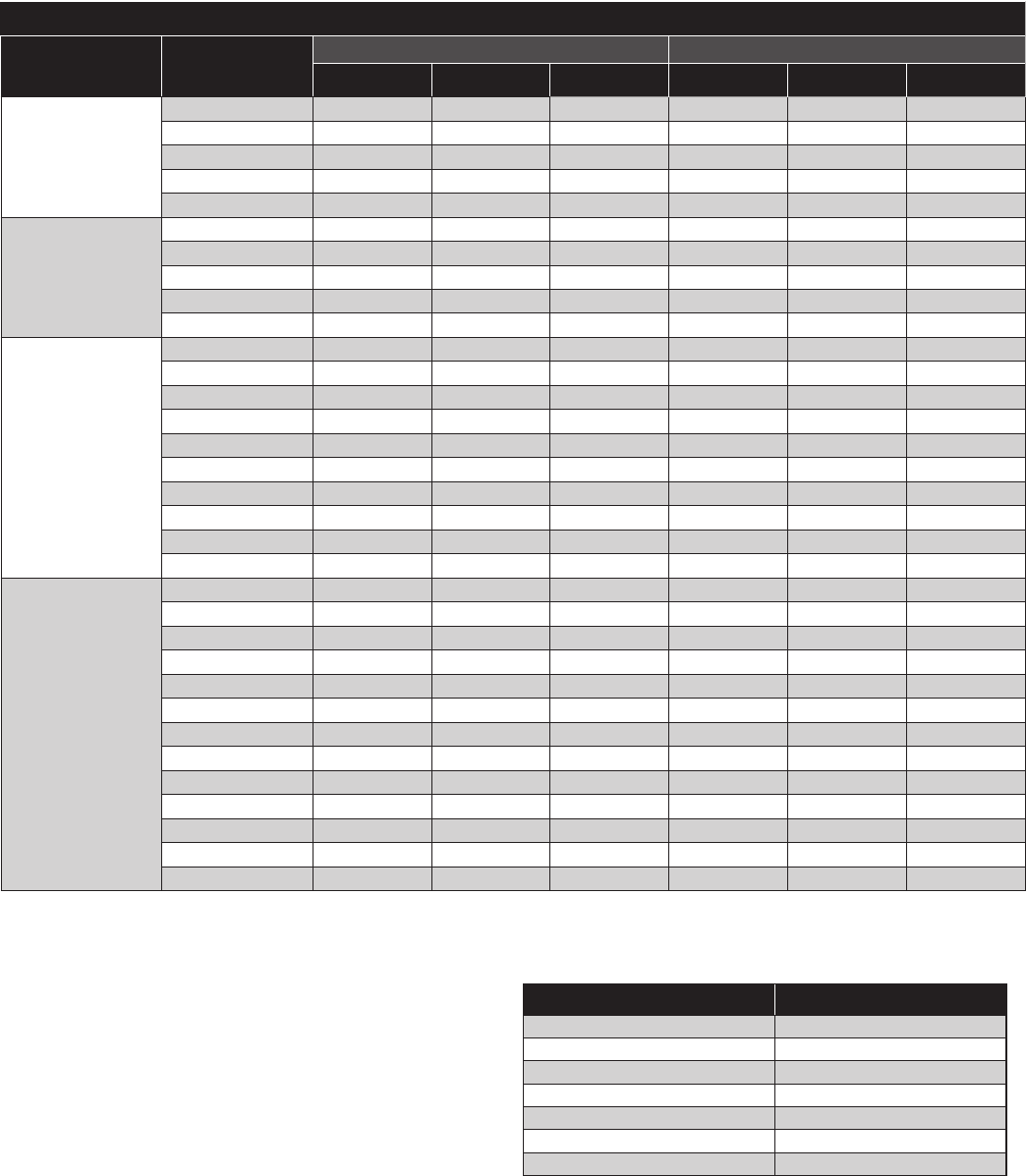
19
Refrigerant Flooding Charge
The following tables summarize the coil charges for High Side products (CU
and ACC).
Winter charge assumes a 90% ooded coil; Summer charge assumes a 10%
ooded coil (For units without subcooling circuit).
Winter charge assumes a 90% ooded coil; Summer charge assumes a 25%
ooded coil (For units with subcooling circuit).
R-404A (lbs)
Group Model
Microchannel RTPF
Summer Winter Additional Summer Winter Additional
Hermetic
Low Temp
#C*0011L^ACH 0.5 1.5 1.0 1.5 3.5 2.0
#C*0014L^ACH 0.5 1.5 1.0 1.5 3.5 2.0
#C*0019L^ACH 1.0 2.0 1.0 2.5 5.5 3.0
#C*0025L^ACH 1.0 2.0 1.0 2.5 5.5 3.0
#C*0031L^ACH 1.0 2.0 1.0 2.5 5.5 3.0
Hermetic
Medium Temp
#C*0015M^ACH 1.0 2.0 1.0 2.5 5.5 3.0
#C*0020M^ACH 1.0 2.0 1.0 2.5 5.5 3.0
#C*0025M^ACH 1.0 2.0 1.0 2.5 5.5 3.0
#C*0030M^ACH 1.5 3.5 2.0 4.5 10.0 5.5
#C*0032M^ACH 1.5 3.5 2.0 4.5 10.0 5.5
Scroll
Low Temp
#C*0006L^ACZ 0.5 1.5 1.0 1.5 3.5 2.0
#C*0008L^ACZ 0.5 1.5 1.0 1.5 3.5 2.0
#C*0010L^ACZ 0.5 1.5 1.0 1.5 3.5 2.0
#C*0022L^ACZ 0.5 1.5 1.0 1.5 3.5 2.0
#C*0025L^ACZ 1.0 2.0 1.0 2.5 5.5 3.0
#C*0030L^ACZ 1.0 2.0 1.0 2.5 5.5 3.0
#C*0035L^ACZ 1.0 2.0 1.0 2.5 5.5 3.0
#C*0045L^ACZ 1.5 3.5 2.0 4.5 10.0 5.5
#C*0055L^ACZ 1.5 3.5 2.0 4.5 10.0 5.5
#C*0060L^ACZ 1.5 3.5 2.0 4.5 10.0 5.5
Scroll
Medium Temp
#C*0005M^ACZ 0.5 1.5 1.0 1.5 3.5 2.0
#C*0008M^ACZ 0.5 1.5 1.0 1.5 3.5 2.0
#C*0009M^ACZ 0.5 1.5 1.0 1.5 3.5 2.0
#C*0010M^A‡Z 0.5 1.5 1.0 1.5 3.5 2.0
#C*0015M^A‡Z 1.0 2.0 1.0 2.5 5.5 3.0
#C*0020M^A‡Z 1.0 2.0 1.0 2.5 5.5 3.0
#C*0025M^A‡Z 1.0 2.0 1.0 2.5 5.5 3.0
#C*0030M^A‡Z 1.5 3.5 2.0 4.5 10.0 5.5
#C*0035M^A‡Z 1.5 3.5 2.0 4.5 10.0 5.5
#C*0045M^A‡Z 1.5 3.5 2.0 4.5 10.0 5.5
#C*0050M^A‡Z 1.5 3.5 2.0 4.5 10.0 5.5
#C*0055M^A‡Z 1.5 3.5 2.0 4.0 10.0 6.0
#C*0060M^A‡Z 1.5 3.5 2.0 4.0 10.0 6.0
These charges are approximate and should not be used as absolute rules
for charging the system.
To determine total system charge, the liquid line and unit cooler must be
taken into account.
Table 9. HTS 1/2 - 6hp (Microchannel Coil)
Refrigerant Charge Factor
R-404A 1.00
R-407A 1.04
R-407C 1.05
R-407F 1.07
R-448A 1.05
R-449A 1.05
R-507A 1.00
NOTES:
# B = Bohn, L = Larkin, C = Climate Control, H = Chandler
* H = Outdoor, N = Indoor
^ B = 208-230/1/60, C = 208-230/3/60, D = 460/3/60
‡ C = Copeland, L = LG
Charge amounts are esitmated operating values only and do not take into account
actual system congurations.
Charge amounts should be adjusted to match actual system requirements.
For refrigerant charges with other refrigerants, use the correction factor table.
Correction Factor Table
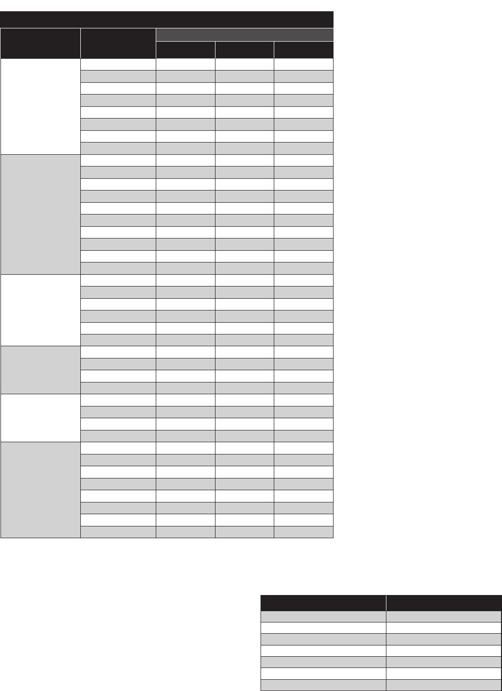
20
Table 10. HCU 1 and 2Fan standard chassis 322hp
R-404A (lbs)
Group Model
RTPF
Summer Winter Additional
Discus
Medium Temp
#C*0050M@ACD 5.0 11.5 6.5
#C*0051M@ACD 5.0 11.5 6.5
#C*0075M@ACD 7.0 15.5 8.5
#C*0076M@ACD 6.5 15.0 8.5
#C*0080M@ACD 8.5 19.5 11.0
#C*0100M@ACD 8.5 19.5 11.0
#C*0120M@ACD 8.5 19.5 11.0
#C*0150M@ACD 12.0 27.0 15.0
Discus
Low Temp
#C*0030L@ACD 3.5 7.5 4.0
#C*0040L@ACD 3.5 7.5 4.0
#C*0060L@ACD 3.5 7.5 4.0
#C*0061L@ACD 3.5 7.5 4.0
#C*0075L@ACD 5.0 11.5 6.5
#C*0090L@ACD 6.5 15.0 8.5
#C*0100L@ACD 6.5 15.0 8.5
#C*0120L@ACD 12.5 27.5 15.0
#C*0150L@ACD 12.5 27.5 15.0
#C*0220L@ACD 12.0 27.5 15.5
Scroll
Medium Temp
#C*0065M@ACZ 7.0 15.5 8.5
#C*0070M@ACZ 6.5 15.0 8.5
#C*0075M@ACZ 9.0 19.5 10.5
#C*0086M@ACZ 8.5 19.5 11.0
#C*0100M@ACZ 8.5 19.5 11.0
#C*0141M@ACZ 12.0 27.0 15.0
Scroll
Low Temp
#C*0075L@ACZ 5.5 11.5 6.0
#C*0100L@ACZ 7.0 15.5 8.5
#C*0130L@ACZ 9.0 19.5 10.5
#C*0150L@ACZ 9.0 19.5 10.5
Bitzer
Medium Temp
#C*0056M@ABX 6.5 15.0 8.5
#C*0076M@ABX 9.0 19.5 10.5
#C*0091M@ABX 12.0 27.5 15.5
#C*0101M@ABX 12.0 27.5 15.5
Bitzer
Low Temp
#C*0041L@ABX 3.5 7.5 4.0
#C*0056L@ABX 5.5 11.5 6.0
#C*0061L@ABX 4.5 10.0 5.5
#C*0062L@ABX 4.5 10.0 5.5
#C*0076L@ABX 6.5 15.0 8.5
#C*0101L@ABX 9.0 20.0 11.0
#C*0121L@ABX 12.5 27.5 15.0
#C*0131L@ABX 12.5 27.5 15.0
Refrigerant Charge Factor
R-404A 1.00
R-407A 1.04
R-407C 1.05
R-407F 1.07
R-448A 1.05
R-449A 1.05
R-507A 1.00
NOTES:
# B = Bohn, L = Larkin, C = Climate Control, H = Chandler
* H = Outdoor, N = Indoor
@
B = 208-230/1/60, C = 208-230/3/60, D = 460/3/60
Charge amounts are esitmated operating values only and do not take into account
actual system congurations.
Charge amounts should be adjusted to match actual system requirements.
For refrigerant charges with other refrigerants, use the correction factor table.
Correction Factor Table
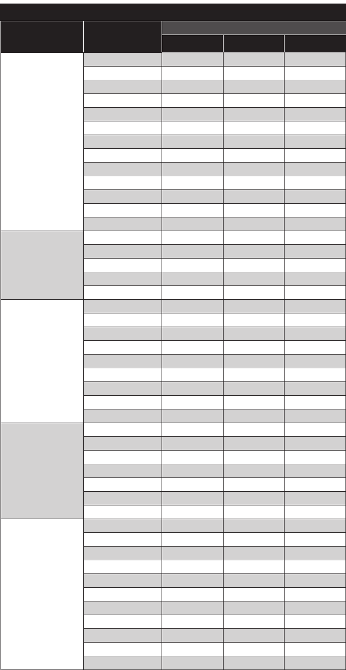
21
R-404A (lbs)
Group Model
RTPF
Summer Winter Additional
Discus
Medium Temp
#CV0150M^ACD 20.5 44.5 24.0
#CV0200M^ACD 20.0 44.5 24.5
#CV0250M^ACD 20.0 44.5 24.5
#CV0260M^ACD 15.0 33.5 18.5
#CV0300M^ACD 20.0 44.5 24.5
#CV0350M^ACD 21.5 49.5 28.0
#CV0400M^ACD 38.0 86.0 48.0
#CV0151M^ACD 15.0 33.5 18.5
#CV0201M^ACD 14.5 33.5 19.0
#CV0251M^ACD 22.0 49.5 27.5
#CV0301M^ACD 29.5 66.5 37.0
#CV0351M^ACD 68.0 153.0 85.0
#CV0401M^ACD 67.0 152.5 85.5
Discus
Low Temp
#CV0120L^ACD 21.0 44.5 23.5
#CV0150L^ACD 21.0 44.5 23.5
#CV0220L^ACD 20.5 44.5 24.0
#CV0270L^ACD 20.5 44.5 24.0
#CV0300L^ACD 20.0 44.5 24.5
Bitzer
Medium Temp
#CV0150M^ABX 15.0 33.5 18.5
#CV0200M^ABX 15.0 33.5 18.5
#CV0220M^ABX 20.0 44.5 24.5
#CV0250M^ABX 20.0 44.5 24.5
#CV0300M^ABX 39.0 86.0 47.0
#CV0330M^ABX 38.5 86.0 47.5
#CV0350M^ABX 52.0 115.0 63.0
#CV0400M^ABX 68.5 153.0 84.5
#CV0500M^ABX 68.0 152.5 84.5
Bitzer
Low Temp
#CV0130L^ABX 15.5 33.5 18.0
#CV0150L^ABX 15.5 33.5 18.0
#CV0200L^ABX 21.0 44.5 23.5
#CV0220L^ABX 15.5 33.5 18.0
#CV0250L^ABX 21.0 44.5 23.5
#CV0300L^ABX 20.5 44.5 24.0
#CV0400L^ABX 54.5 115.0 60.5
Mohave
Medium Temp
#CM0077M^ACD 28.5 58.0 29.5
#CM0078M^ACD 28.0 58.0 30.0
#CM0082M^ACD 38.0 77.5 39.5
#CM0102M^ACD 37.5 77.5 40.0
#CM0122M^ACD 37.0 77.5 40.5
#CM0152M^ACD 27.0 58.0 31.0
#CM0202M^ACD 36.0 77.0 41.0
#CM0252M^ACD 39.5 86.5 47.0
#CM0302M^ACD 39.0 86.0 47.0
#CM0352M^ACD 52.0 115.0 63.0
#CM0402M^ACD 52.0 114.5 62.5
Table 11. (D)VCU 12-110hp
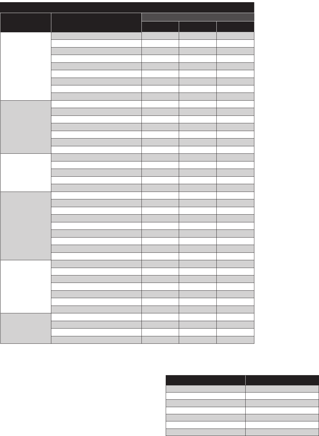
22
R-404A (lbs)
Group Model
RTPF
Summer Winter Additional
Mohave
Low Temp
#CM0062L^ACD 30.0 58.0 28.0
#CM0077L^ACD 39.5 77.5 38.0
#CM0092L^ACD 39.0 77.5 38.5
#CM0102L^ACD 38.5 77.5 39.0
#CM0122L^ACD 38.5 77.5 39.0
#CM0152L^ACD 38.0 77.5 39.5
#CM0222L^ACD 37.5 77.5 40.0
#CM0272L^ACD 37.0 77.5 40.5
#CM0302L^ACD 36.5 77.5 41.0
Dual-Discus
Medium Temp
#CD0300M^ACD 41.0 89.0 48.0
#CD0400M^ACD 40.5 89.0 48.5
#CD0500M^ACD 40.0 89.0 49.0
#CD0520M^ACD 29.5 66.5 37.0
#CD0600M^ACD 39.5 89.0 49.5
#CD0700M^ACD 43.0 99.5 56.5
#CD0800M^ACD 76.0 172.0 96.0
Dual-Discus
Low Temp
#CD0240L^ACD 42.0 89.5 47.5
#CD0300L^ACD 41.5 89.5 48.0
#CD0440L^ACD 41.0 89.5 48.5
#CD0540L^ACD 41.0 89.0 48.0
#CD0600L^ACD 40.0 89.5 49.5
Dual-Bitzer
Medium Temp
#CD0300M^ABX 32.5 67.0 34.5
#CD0400M^ABX 32.0 67.0 35.0
#CD0440M^ABX 43.5 89.5 46.0
#CD0500M^ABX 43.0 89.5 46.5
#CD0600M^ABX 83.5 173.0 89.5
#CD0660M^ABX 83.5 173.0 89.5
#CD0700M^ABX 112.0 231.0 119.0
#CD0800M^ABX 147.0 306.5 159.5
#CD1100M^ABX 145.0 306.5 161.5
Dual-Bitzer
Low Temp
#CD0260L^ABX 31.5 67.0 35.5
#CD0300L^ABX 31.0 67.0 36.0
#CD0400L^ABX 41.5 89.5 48.0
#CD0440L^ABX 31.0 67.0 36.0
#CD0500L^ABX 41.5 89.0 47.5
#CD0600L^ABX 41.0 89.0 48.0
#CD0800L^ABX 109.0 230.5 121.5
Dual-Discus
Medium Temp
(Alternate (Non-EC))
#CD0520M^ACD, Alternate (non-EC) 29.5 66.5 37.0
#CD0600M^ACD, Alternate (non-EC) 39.5 89.0 49.5
#CD0700M^ACD, Alternate (non-EC) 43.0 99.5 56.5
#CD0800M^ACD, Alternate (non-EC) 76.0 172.0 96.0
Table 12. (D)VCU 12-110hp (cont.)
Refrigerant Charge Factor
R-404A 1.00
R-407A 1.04
R-407C 1.05
R-407F 1.07
R-448A 1.05
R-449A 1.05
R-507A 1.00
NOTES:
# B = Bohn, L = Larkin, C = Climate Control, H = Chandler
^ C = 208-230/3/60, D = 460/3/60, K = 230/3/60, E = 575/3/60
Charge amounts are esitmated operating values only and do not take into account
actual system congurations.
Charge amounts should be adjusted to match actual system requirements.
For refrigerant charges with other refrigerants, use the correction factor table.
Correction Factor Table
23
Check Out and Start Up
After the installation has been completed, the following points should be
covered before the system is placed in operation:
a) Check all electrical and refrigerant connections.
Be sure they are all tight.
b) Observe compressor oil level before start-up. The oil level should
be at or slightly above the 1/4 level
of the sight glass. Refer to
compressor manufacturers OEM instruction and operations
manual for oil specications before adding.
c) Remove upper mounting nuts on the compressor feet.
Remove the shipping spacers. Install the neoprene washers onto
the compressor feet. Replace the upper mounting nuts
and washers, allowing 1/16" space between the mounting nut
and the neoprene spacer.
d) Check high and low pressure controls, pressure regulating valves,
oil pressure safety controls, and all other safety controls, and
adjust if necessary.
e) Check the room thermostat for normal operation
and adjust.
f) Wiring diagrams, instruction bulletins, etc. attached to the
condensing units should be read and led for future reference.
g) All fan motors should be checked for proper rotation. Fan
motor mounts should be carefully checked for tightness and
proper alignment.
h) Electric and hot gas evaporator fan motors should
be temporarily wired for continuous operation until
the room temperature has stabilized.
i) Observe system pressures during charging and initial operation.
Do not add oil while the system is short of refrigerant
unless oil level is dangerously low.
j) Continue charging until system has sucient refrigerant for
proper operation. Do not overcharge.
Remember that bubbles in a sight glass may be caused by
a restriction as well as a shortage of refrigerant.
k) Do not leave unit unattended until the system has
reached normal operating conditions and the oil
charge has been properly adjusted to maintain the oil
level between 1/4 and bottom of the sight glass.
l) Make sure all Schrader valve caps are in place and tight.
m) Make sure ALL service valves are properly back-seated and tighten
valve packing if necessary.
CAUTION:
Extreme care must be taken in starting compressors for the rst time
after system charging. At this time, all of the oil and most of the
refrigerant might be in the compressor creating a condition which could
cause compressor damage due to slugging. Activating the crankcase
heater for 24 hours prior to start-up is required. If no crankcase heater is
present, then directing a 500 watt heat lamp or other safe heat source on
the lower shell of the compressor for approximately thirty minutes will be
benecial in eliminating this condition which might never reoccur.
WARNING:
Scroll compressor is directional dependent. If noisy, change phase of
input wiring.
Field Wiring
WARNING:
All wiring must be done in accordance with applicable codes and local
ordinances.
The eld wiring should enter the areas as provided on the unit. The wiring
diagram for each unit is located on the inside of the electrical panel door.
All eld wiring should be done in a professional manner and in accordance
with all governing codes. Before operating unit, double check all wiring
connections, including the factory terminals. Factory connections can vibrate
loose during shipment.
1. The serial data tag on the unit is marked with the electrical characteristic
for wiring the unit.
2. Consult the wiring diagram in the unit cooler and in the condensing unit
for proper connections.
3. Wire type should be of copper conductor only and of the proper
size to handle the connected load.
4. The unit must be grounded.
5. For multiple evaporator systems, the defrost termination controls
should be wired in series. Follow the wiring diagrams for multiple
evaporator systems carefully. This will assure complete defrost of
all evaporators in the system.
6. Multiple evaporator systems should operate o of one thermostat.
7. If a remote defrost timer is to be used, the timer should be located
outside the refrigerated space.
8. For air cooled condensers, due to multiple low amp motors, we
recommend using time delay fuse protection instead
of circuit breakers.
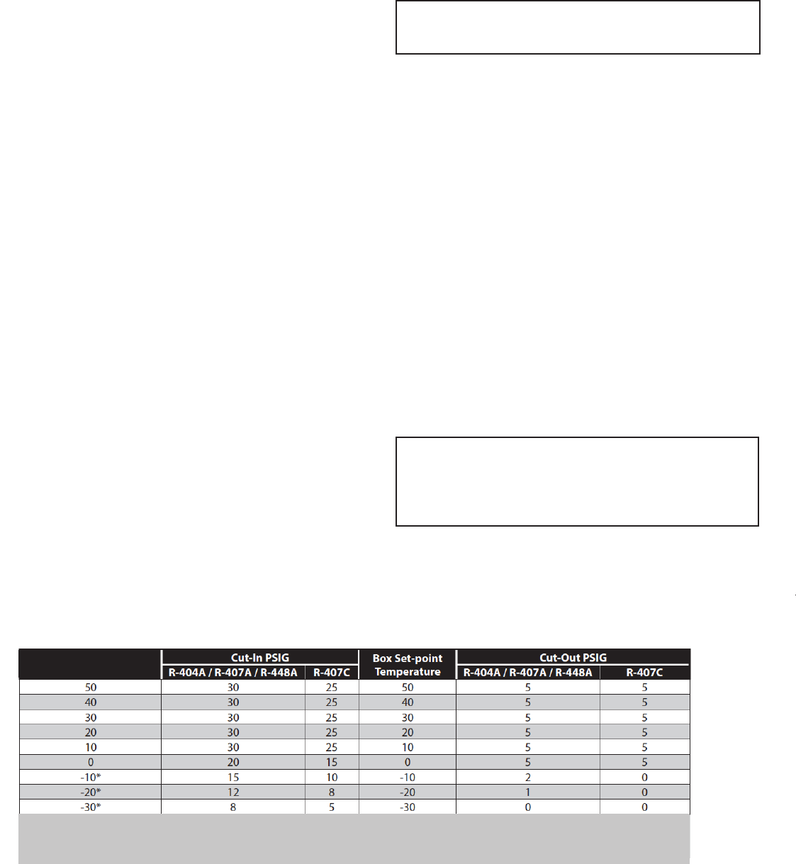
24
System Balancing - Compressor Superheat
IMPORTANT:
In order to obtain the maximum capacity from a system, and to ensure
trouble-free operation, it is necessary to balance each and every system.
This is extremely important with any refrigeration system.
The critical value which must be checked is suction superheat.
Suction superheat should be checked at the compressor as follows:
1. Measure the suction pressure at the suction service valve of the
compressor and determine the saturation temperature corresponding
to this pressure from a “Temperature-Pressure” chart.
2. Measure the suction temperature of the suction line about one
foot back from the compressor using an accurate thermometer.
3. Subtract the saturated temperature from the actual
suction line temperature. The dierence is superheat.
Too low a suction superheat can result in liquid being returned to the
compressor. This will cause dilution of the oil and eventual failure of the
bearings and rings or in the extreme case, valve failure.
Too high a suction superheat will result in excessive discharge temperatures
which cause a break down of the oil and results in piston ring wear, piston
and cylinder wall damage.
It should also be remembered that the system capacity decreases as the
suction superheat increases. For maximum system capacity, suction
superheat should be kept as low as is practical. We recommend that
the superheat at the compressor be between 20˚F and 30˚F, to meet
compressor manufacture guidelines.
If adjustments to the suction superheat need to be made, the expansion
valve at the evaporator should be adjusted.
Operational Check Out
After the system has been charged and has operated for at least two hours at
normal operating conditions without any indication of malfunction, it should
be allowed to operate overnight on automatic controls. Then a thorough
recheck of the entire system operation should be made as follows:
a) Check compressor discharge and suction pressures.
If not within system design limits, determine why and
take corrective action.
b) Check liquid line sight glass and expansion valve operation. If
there are indications that more refrigerant is required, leak test
all connections and system components and repair any
leaks before adding refrigerant.
c) Observe oil level in compressor crankcase sight glass. Add oil as
necessary to bring level to bottom 1/4 of the sight glass.
d) Thermostatic expansion valves must be checked
for proper superheat settings. Feeler bulbs must be
in positive contact with the suction line and should
be insulated. Valves set at high superheat will lower
refrigeration capacity. Low superheat promotes
liquid slugging and compressor bearing washout.
e) Using suitable instruments, carefully check line voltage and
amperage at the compressor terminals. Voltage must be within
10% of that indicated on the condensing unit nameplate. If high
or low voltage is indicated, notify the power company.
If amperage draw is excessive, immediately determine the cause
and take corrective action. On three phase motor compressors,
check to see that a balanced load is drawn
by each phase.
f) The maximum approved settings for high pressure controls on
our air cooled condensing equipment is 425 psig. On air cooled
systems, check as follows:
Disconnect the fan motors or block the condenser inlet air. Watch
high pressure gauge for cutout point. Recheck all safety and
operating controls for proper operation and adjust if necessary.
g) Check defrost controls for initiation and termination settings, and
length of defrost period. Set fail safe at length of defrost + 25%.
Example: 20 minute defrost + 5 minutes = 25 minute fail safe
h) Check drain pan for proper drainage.
i) Check winter head pressure controls for pressure setting.
j) Check crankcase heater operation if used.
k) Install instruction card and control system diagram for
use of building manager or owner.
Table 13. Recommended Low Pressure Control Settings for Outdoor Air Cooled Condensing Units
Minimum Expected
Ambient Temperature
# Minimum ambient or box temperature anticipated, high pressure control setting: R-22, 360 PSI; R404-A, R-507, R-407A, R-407C, R-407F, R-448A, 400 PSI
*Low Ambient Kit should be considered to assist compressor start-up.
(1) The standard preset low pressure switch used for pumpdown is set for 15 PSIG cut-in / 5 PSIG cut-out and is a good setting for most pumpdown systems
(2) ZB Scroll compressors should be set for 35 PSI cut-in / 17 PSI cut-out (R404A/R507) and 27 PSI cut-in / 9 PSI cut-out (R407A/R407C/R448A)
(3) Models with ZB Scroll compressors may require a low ambient kit to start reliably at ambient temperatures below 20°F.
Minimum Expected
Ambient Temperature#
NOTE:
Most adjustable controls have to be eld adjusted to meet desired
operation. This includes low pressure, high pressure, pressure fan
cycling, adjustable dual valve head pressure systems and expansion
valves. Exceptions are adjustable single valve head pressure valves
which are pre-set.
25
Copeland Demand Cooling for Discus L6 Models
Energy eciency regulations drive continuous change in the availability
of refrigerants to the marketplace. With the introduction of R-22 as a
replacement for R-502, compressors began to experience internal discharge
temperatures that exceed the safe operational limits for long term stability
of refrigerant oil. In response to this, Demand Cooling was developed as
a reliable method to keep discharge temperatures reduced to a safe level
without inhibiting the operating limits of the compressor. With the phase
out of R-22, the following refrigerants have become viable alternatives:
R-407A/C/F and R-448A/R-449-A. All of these refrigerants require special
attention to discharge temperature control. Also for this reason suction to
liquid heat exchangers are not recommended unless they are necessary to
prevent another potential problem.
General Sequence of Operation
Refrigeration Cycle
1. Power is supplied to the timer at terminals “1” and “N”.
2. The fan delay and the defrost termination thermostat is closed in the fan
delay position and open in the defrost termination position.
The unit cooler fans run continuously.
3. The defrost heaters are o.
4. The room thermostat closes when the temperature rises above the
desired setting.
5. The liquid line solenoid is energized and opens, which allows
liquid refrigerant to ow through the unit cooler.
6. The low pressure control closes when the suction pressure rises
above the cutin setting of the control.
7. On systems with oil pumps, the oil safety control is closed. If the
net oil pressure is less than 9 PSIG for more than 120
seconds, the oil safety opens, thus breaking the circuit
to the compressor contactor holding coil. The compressor will
not operate. This control is reset manually and must be
reset before the compressor can be restarted.
8. The compressor contactor closes. The compressor and condenser
fan start simultaneously.
9. The room temperature gradually decreases to the desired temperature.
10. Once the desired temperature is reached, the thermostat opens and the
liquid line solenoid closes, stopping refrigerant ow through
the evaporator.
11. Suction pressure decreases and the compressor contactor opens
when the pressure drops below the cutout setting on the low
pressure control. The compressor and condenser fan stop running.
12. This cycle is repeated as many times as necessary to satisfy the
room thermostat.
13. Frost starts to form on the evaporator coil and continues to form
until the defrost cycle is initiated.
Defrost Cycle
1. The defrost cycle starts automatically by the timer at predetermined
times. Typical settings are two to four defrost cycles per day for freezers.
For heavier frost loads additional settings may be required.
2. Switch “2” to “4” opens in the timer which breaks the circuit to the room
thermostat, liquid line solenoid, and evaporator fan motors, allowing
the compressor to pump down and shut o. Simultaneously
switch “1” to “3” closes in the timer allowing current to ow to one side
of the defrost heater contactor. When the compressor
shuts o, an auxiliary contact will send power to the contactor holding
coil; thus, energizing the defrost heaters.
3. The heaters raise the temperature of the coil to 32˚F causing the frost to
melt o the coil.
4. When the coil warms to 45˚F to 55˚F, the defrost termination thermostat
closes, which allows current to the switching solenoid in the timer
allowing the refrigeration cycle to begin again.
5. The evaporator heaters are o. If the termination thermostat fails to
close, the fail-safe set on the timer will terminate defrost.
6. The low pressure control closes and the compressor will start.
7. When the coil temperature reaches 23˚F to 30˚F, the fan
delay closes. This allows the current to ow to the fan
motors. The fan motors start running.
8. The system will now operate in the refrigeration cycle until another
defrost period is initiated by the timer.
The Copeland Demand Cooling System
It is required for all single stage R-22, R-407A/C/F or R-448A/R-449-A
applications with saturated suction temperatures below 0˚F.
The Demand Cooling module uses the signal of a discharge head temperature
sensor to monitor discharge gas temperature. If a critical temperature is
reached, the module energizes along life injection valve which meters a
controlled amount of saturated refrigerant into the compressor suction
cavity to cool the suction gas.
This process controls the discharge temperature to a safe level. If for some
reason the discharge temperature rises above a preset maximum level,
the Demand Cooling module will turn the compressor o (requiring a
manual reset) and actuate its alarm contact. To minimize the amount of
refrigerant which must be injected, the suction gas cooling process is
performed after the gas has passed around and through the motor.
Operating Range
Demand Cooling is designed to protect the compressor from high discharge
temperatures over the evaporating and condensing temperature ranges
shown in Figure 12 at a maximum return gas temperature of 65˚F.
Demand Cooling System Design
When Demand Cooling operates, it “diverts” refrigeration capacity in the
form of injected saturated refrigerant from the evaporator to the compressor.
1. Compressor Return Gas Temperature: Suction lines should be well
insulated to reduce suction line heat gain. Return gas superheat
should be as low as possible consistent with safe compressor
operation.
2. Condensing Temperatures: It is important when using R-22, R-407
A/C/F or R-448A/449A as a low temperature refrigerant that
condensing temperatures be minimized to reduce compression ratios
and compressor discharge temperature.
3. Suction Pressure: Evaporator design and system control settings
should provide the maximum suction pressure consistent with the
application in order to have as low a compression ratio as possible.
In most cases, with oating head systems where condensing temperatures
are low during most of the year, Demand Cooling will operate primarily as
a compressor protection control much as the oil failure control protects the
compressor during periods of low oil pressure. Demand Cooling will be
allowed to operate only during those periods when condensing temperatures
and return gas temperatures are high or in periods where a system failure
(such as an ice evaporator, an expansion valve which does not control
superheat, blocked condenser, or a failed condenser fan) raises condensing
temperatures or return gas temperatures to abnormally high levels or lowers
suction pressure to abnormally low levels.
26
Electric Defrost Troubleshooting
The electric defrost units are relatively simple and trouble-free in operation:
Timer
If the system does not go through its proper sequence , check timer
operation through a defrost cycle. Check for loose wires or terminals. Before
replacing timer, check other components.
Operation of Paragon Timer
To set time of day grasp knob which is in the center of the inner (fail-safe) dial
and rotate it in a counter-clockwise direction. This will cause the outer (24
hour) dial to revolve. Line up the correct time of day on the outer dial with
the time pointer. Do not try to set the time control by grasping the other (24
hour) dial. Place pins in the outer dial at the time of day that defrost
is required.
Operation of Electronic Timer
To set the time, turn the minute hand clockwise until the time of day (and
AM or PM) on the outer dial is aligned with the triangle marker on the inner
dial. Do not rotate minute hand counter-clockwise. Move the white tab
(tripper) on the outer dial outward at each desired initiation time. Each white
tab (tripper) is a 15 minute interval and provides 15 minutes of defrost. For
longer defrost duration, move additional tabs (following in time) from the
initiation tab. For example, if a 45 minute defrost is to start at 7:00 AM, move
the tabs outward that lie between 7:00 - 7:15, 7:15 - 7:30 and 7:30 - 7:45 on
the AM side of the dial. The defrost will initiate at 7:00 AM and time terminate
at 7:45 AM (if temperature termination does not occur rst). For models with
plastic cover on timer assembly; re-install cover after adjustment.
NOTE:
After correcting faulty condition it is essential that the coil and unit be
free of ice before placing unit back on automatic operation.
NOTES:
1. Lockout relays or normally closed switch of auxiliary contact on the
compressor contactor may be wired to defrost contactor. Its purpose
is to prevent energizing of the defrost heaters until the compressor has
pumped down and stopped, thus keeping power demand to a minimum.
2. If the control voltage is to remain energized for any period of time with
the compressor disabled, remove the defrost clock pins to prevent the
defrost heaters from energizing.
3. A Preventative Maintenance schedule should be set up as soon as
possible after start-up to maintain equipment integrity.
The Orbus Controller measures system head pressure, compares the
measurements to the head pressure set point, and through a proprietary
algorithm outputs a 0-10V signal to the variable speed EC Motor. The Orbus
board requires a 24VAC for operation. The controller has two predened set
points selectable by a jumper. For R-404A systems the set point is 150 psig.
To diagnose issues it has a blinking LED that will provide status/error codes
to aid in troubleshooting.
Optional Variable Speed EC Motor with Orbus
Controller
How does the Orbus Controller work?
Orbus is a simple way for variable speed head pressure control. It reads
the system pressure via a transducer and then outputs a 0-10 VDC signal
that is linearly proportional to fan speed. All of the communication elec-
tronics necessary for variable speed are built into the motor housing. To
control the speed of the motor, an analog signal (0-10VDC) is supplied to
the motor. The motor interprets the analog signal and changes the speed
proportionally to match the input signal.
Sensor
Requires 0-500 psig pressure transducer
• Transducer should supply 0.5VDC at 0 psig
• Transducer should supply 4.5VDC at 500 psig
Jumpers
• Jumper #1 – 150 psig, 100 throttling range
• Jumper #2 – 125 psig, 100 throttling range
• Jumper #3 – 100 psig, 100 throttling range
• All three – Test condition, output ramps up and down
0
50
100
150
200
250
300
350
400
450
500
0.0 0.5 1.0 1.5 2.0 2.5 3.0 3.5 4.0 4.5 5.0
Volts
Pressure (psig)
0
50
100
150
200
250
300
350
400
450
500
0.0 0.5 1.0 1.5 2.0 2.5 3.0 3.5 4.0 4.5 5.0
Volts
Pressure (psig)
VO LT S
PRESSURE (psig)
Status LED
• Control board status is indicated by a multi-color LED
• On startup, LED cycles from red to yellow to green
• Blinking green means everything ok
• Length of ash is an indicator of speed
• Short on, long o indicates low speed
• Long on, short o indicates high speed
• Alternating green and one red
• Transducer is missing, open or shorted
• Fan runs full speed
• Alternating green and two red
• Main oscillator dead, running on backup
• Normal function still available
• Three reds in a row indicate both oscillator failure and transducer failure
Troubleshooting
• To check transducer operation, measure DC voltage between Signal
and Common
• Compare transducer value to pressure measured using gage set
• Unplugging sensor will cause output to be 0VDC and should produce
one red blink
• If system pressure is above set point plus throttling range, control
board should output 0VDC
• If system pressure is below set point, control board should output 10VDC
Diagram 5
27
ORBUS™ CONTROL BOARD
Jumpers
Status LED
Output
Sensor
24 VAC

28
Table 14. System Troubleshooting Chart
PROBLEM POSSIBLE CAUSES POSSIBLE CORRECTIVE STEPS
Compressor will not
run
1. Main switch open.
2. Fuse blown.
3. Thermal overloads tripped.
4. Defective contactor or coil.
5. System shut down by safety devices.
6. No cooling required.
7. Liquid line solenoid will not open.
8. Motor electrical trouble.
9. Loose wiring.
10. Phase loss monitor inoperative.
1. Close switch.
2.
Check electrical circuits and motor winding for shorts or grounds.
Investigate for possible overloading. Replace fuse after fault is corrected.
3. Overloads are automatically reset. Check unit closely when unit
comes back on line.
4. Repair or replace.
5. Determine type and cause of shutdown and correct it before
resetting safety switch.
6. None. Wait until calls for cooling.
7. Repair or replace coil.
8. Check motor for open windings, short circuit or burn out.
9. Check all wire junctions. Tighten all terminal screws.
10. Refer to page 23.
Compressor noisy or
vibrating
1. Flooding of refrigerant into crankcase.
2. Improper piping support on suction or liquid line.
3. Worn compressor.
4. Scroll compressor rotation reversed.
1. Check setting of expansion valves.
2. Relocate, add or remove hangers.
3. Replace.
4. Rewire for phase change.
High discharge
pressure
1. Non-condensables in system.
2. System overcharges with refrigerant.
3. Discharge shutoff valve partially closed.
4. Fan not running.
5. Head pressure control setting.
6. Dirty condenser coil.
1. Remove the non-condensables.
2. Remove excess.
3. Open valve.
4. Check electrical circuit.
5. Adjust.
6. Clean.
Low discharge
pressure
1. Faulty condenser temperature regulation.
2. Suction shutoff valve partially closed.
3. Insufficient refrigerant in system.
4. Low suction pressure.
5. Variable head pressure valve.
1. Check condenser control operation.
2. Open valve.
3. Check for leaks. Repair and add charge.
4. See corrective steps for low suction pressure.
5. Check valve setting.
High suction
pressure
1. Excessive load.
2. Expansion valve overfeeding.
1. Reduce load or add additional equipment.
2. Check remote bulb. Regulate superheat.
Low suction pressure 1. Lack of refrigerant.
2. Evaporator dirty or iced.
3. Clogged liquid line filter drier.
4. Clogged suction line or compressor suction gas strainers.
5. Expansion valve malfunctioning.
6. Condensing temperature too low.
7. Improper TXV.
1. Check for leaks. Repair and add charge.
2. Clean.
3. Replace cartridge(s).
4. Clean strainers.
5. Check and reset for proper superheat.
6. Check means for regulating condensing temperature.
7. Check for proper sizing.
Little or no oil
pressure
1. Clogged suction oil strainer.
2. Excessive liquid in crankcase.
3. Low oil pressure safety switch defective.
4. Worn oil pump.
5. Oil pump reversing gear stuck in wrong position.
6. Worn bearings.
7. Low oil level.
8. Loose fitting on oil lines.
9. Pump housing gasket leaks.
1. Clean.
2. Check crankcase heater. Reset expansion valve for higher superheat.
Check liquid line solenoid valve operation.
3. Replace.
4. Replace.
5. Reverse direction of compressor rotation.
6. Replace compressor.
7. Add oil and/or through defrost.
8. Check and tighten system.
9. Replace gasket.
Compressor loses oil 1. Lack of refrigerant.
2. Excessive compression ring blow by.
3. Refrigerant flood back.
4. Improper piping or traps.
1. Check for leaks and repair. Add refrigerant.
2. Replace compressor.
3. Maintain proper superheat at compressor.
4. Correct piping.
Compressor thermal
protector switch
open
1. Operating beyond design conditions.
2. Discharge valve partially shut.
3. Blown valve plate gasket.
4. Dirty condenser coil.
5. Overcharged system.
1. Add components to bring conditions within acceptable limits (i.e.,
CPR/EPR valves, additional condenser surface, liquid injection, etc.).
2. Open valve.
3. Replace gasket.
4. Clean coil.
5. Reduce charge.
System does not
start reliably in
cold weather.
(Low pressure switch
not closing
1. Low pressure switch not correctly adjusted.
2. Low ambient kit not installed.
1. Adjust low pressure switch (see page 24)
2. Install low ambient kit (low pressure switch settings can be lowered
temporarily to allow system to start)
3. Review " low suction pressure possible causes".
4. Call Heatcraft tech support.
29
Commercial Refrigeration Parts
Replacement Parts by
InterLink™ Comercial Refrigeration Parts is your link to a complete line of dependable and certied commercial refrigeration parts, accessories
and innovative electronic controls for all Heatcraft Refrigeration Products (HRP) brands - including Bohn, Larkin, Climate Control and Chandler.
At InterLink, we provide our wholesalers with a comprehensive selection of product solutions and innovative technologies for the installed
customer base. And every product is built to ensure the same high performance standards with which all HRP brands are built — backed by a
dedicated team to serve every customer need, delivering at the best lead times in the industry.
Replacement parts should be obtained from your local InterLink wholesaler. Replacement parts, which are covered under the terms of the
warranty statement on page 2 of this manual, will be reimbursed for total part cost only. The original invoice from the parts supplier must
accompany all warranty claims for replacement part reimbursement. Heatcraft Refrigeration Products reserves the right to adjust the
compensation amount paid on any parts submitted for warranty reimbursement when a parts supplier's original invoice is not provided with a
claim. For more information, call 800-686-7278 or visit www.interlinkparts.com.
System will not
run reliably in
cold weather.
(Short cycling on low
pressure switch)
1. Low pressure switch not correctly adjusted.
2. Lack of refrigerant.
3. Low ambient kit not installed.
1. Adjust low pressure switch (see page 24)
2. Check for leaks. Repair and add charge.
3. Install pressure fan cycling control to reduce the time required to
reach the head pressure valve setpoint. The control operation shall
not defeat the head pressure valve setpoint. See Table 15.
4. Call Heatcraft tech support.
System will not
run reliably in
cold weather.
(Head pressure does
not reach minimum
setting during
cooling cycle
1. Lack of refrigerant.
2. Head pressure builds too slowly to reach setpoint during
cooling cycle.
3. Head pressure valve defective.
1. Check for leaks. Repair and add charge.
2. Install pressure fan cycling control to reduce the time required to
reach the head pressure valve setpoint. The control operation shall
not defeat the head pressure valve setpoint. See Table 15.
3. Replace head pressure valve.
Low compressor
superheat observed
at compressor in
cold weather.
1. Unit cooler has ice accumulation
2. Superheat low when measured at unit cooler.
3. Suction accumulator not installed.
1. Defrost unit cooler completely.
2. Raise superheat at unit cooler by 5°F (3°C).
3. Install suction accumulator
Slow initial room
pull-down in cold
weather.
1. Expansion valve capacity less than pull-down
load.
2. Expansion valve not sized for minimum head pressure
and the installed distributor nozzle.
1. Temporarily reduce the condenser coil face area to elevate the
discharge pressure to equivalent 105°F condensing temperature
during pull-down. (Remove blockage after pull-down).
2. Replace expansion valve with correct size.
Table 14. System Troubleshooting Chart (cont.)
PROBLEM POSSIBLE CAUSES POSSIBLE CORRECTIVE STEPS
Head Pressure Valve Setpoint Control cut-in setting psi Control cut-out setting psi
150 psi
175
140
100 psi
125
90
NOTE: Use pressure fan cycling for fan nearest compressor. Use ambient fan cycling (see Table 1) for other fans
Table 15. Pressure Fan Cycling Recommended Settings

30
Preventive Maintenance Guidelines
Air-Cooled Condensing Units
Quarterly
1) Visually inspect unit
• Look for signs of oil stains on interconnection piping and condenser
coil. Pay close attention to areas around solder joints, building
penetrations and pipe clamps. Check any suspect areas with an
electronic leak detector. Repair any leaks found and add refrigerant as
needed.
• Check condition of moisture indicator/sightglass in the sight glass if
so equipped. Replace liquid line drier if there is indication of slight
presence of moisture. Replace refrigerant, oil and drier if moisture
concentration is indicated to be high.
• Check moisture indicator/sightglass for ash gas. If found check
entire system for refrigerant leaks and add refrigerant as needed after
repairing any leaks.
• Check compressor sightglass (if equipped) for proper oil level.
• Check condition of condenser. Look for accumulation of dirt and debris
(clean as required).
• Check for unusual noise or vibration. Take corrective action as required.
• Inspect wiring for signs of wear or discoloration and repair if needed.
• Check and tighten all are connections.
Semi-Annually
2) Repeat all quarterly inspection items.
3) Clean condenser coil and blades
• Periodic cleaning can be accomplished by using a brush, pressurized
water and a commercially available foam coil cleaner. If foam cleaner is
used, it should not be an acid based cleaner. Follow label directions for
appropriate use.
• Rinse until no residue remains.
4) Check operation of condenser fans
• Check that each fan rotates freely and quietly. Replace any fan motor
that does not rotate smoothly or makes excessive noise.
• Check all fan blade set screws and tighten as required.
• Check all fan blades for signs of cracks, wear or stress. Pay close
attention to the hub and spider. Replace blades as required.
• Verify that all motors are mounted securely.
• Lubricate motors if applicable. Do not lubricate permanently sealed,
ball bearing motors.
5) Inspect electrical wiring and components
• Verify that all electrical and ground connections are secure, tighten as
required.
• Check condition of compressor and heater contactors. Look for
discoloration and pitting. Replace as required.
• Check operation and calibration of all timers, relays pressure controls
and safety controls.
• Clean electrical cabinet. Look for signs of moisture, dirt, debris, insects
and wildlife. Take corrective action as required.
• Verify operation of crankcase heater by measuring amp draw.
6) Check refrigeration cycle
• Check suction, discharge and net oil pressure readings. If abnormal take
appropriate action.
• Check operation of demand cooling, liquid injection or unloaders if so
equipped.
• Check pressure drop across all lters and driers. Replace as required.
• Verify that superheat at the compressor conforms to specication. (30°F
to 45°F)
• Check pressure and safety control settings and verify proper operation.
Annually
7) In addition to quarterly and semiannual maintenance checks, submit an
oil sample for analysis
• Look for high concentrations of acid or moisture. Change oil and driers
until test results read normal.
• Investigate source of high metal concentrations, which normally
are due to abnormal bearing wear. Look for liquid refrigerant in the
crankcase, low oil pressure or low superheat as a possible source.
8) Inspect suction accumulator (if equipped)
• If the accumulator is insulated remove insulation and inspect for leaks
and corrosion.
• Pay close attention to all copper to steel brazed connections
• Wire brush all corroded areas and peeling paint.
• Apply an anticorrosion primer and paint as required. Re-insulate if
applicable.
31
C
A
SHEET METAL
CUT SIZE-----------------------
u
.03
HOLE DIAMETER------------
u
.005
ENDPLATE TUBE HOLE---
u
.001
C/L OF HOLES-----------------
u
.02
ANGLES--------------------------±2°
FORMED DIMENSIONS
0 TO 36---------------------------±.03
36 TO 120----------------------- ±.06
OVER 120------------------------±.13
COIL ASSEMBLY
FINNED LENGTH
0 TO 24------------------
u
.06
24 TO 75----------------
u
.13
OVER 75----------------
u
.19
CONNECTIONS-------±13
FIN QUANT ITY--------±3%
BOW (ANY DIRECTION)
12 TO 36---------------- ±.13
36 TO 96-----------------±.19
OVER 96------------------±.25
WIRE & CONDUIT
(NOT UNDER TENSION)
WIRE CUT SIZE-----+.50/-.00
CONDUIT CUT SIZE
0 TO 12-----------------+.13/-.00
12 TO 36---------------+.38/-.00
OVER 36---------------+.75/-.00
TOLERANCES (UNLESS
OTHERWISE SPECIFIED)
THIS DOCUMENT CONTAINS MATERIAL AND/OR
INFORMATION WHICH IS THE PROPERTY OF
HEATCRAFT REFRIGERATION PRODUCTS AND IS
SUPPLIED ONLY ON A PROPRIETY BASIS. NO
TRANSMITTAL SHALL BE MADE TO ANY PERSON,
FIRM, OR CORPORATION WITHOUT PRIOR
WRITTEN APPROVAL.
TOLERANCE BLOCK
REVISED 03/05/2014 REV. B
-
-
1 OF 1
TITLE:
PRODUCT:
PART NO.:
29613714
DWG. NO.:
29613714
REV.
SHEET
DRAWN DATE
REFRIGERATION PRODUCTS LLC
STONE MOUNTAIN, GEORGIA
U.S.A.
--
TUBING
FRACTIONAL----
u
.03
1 TO 36-------------
u
.06
OVER 36------------
u
.13
ANGLES------------±5°
3rd
v
PROJECTION
--------
-
-
APPROVED DATE
REVISIONS
REV ECM BY DATE DESCRIPTION
A N/A AJP 5/22/17 REV. FIELD MTD OR BY OTHERS DET.'S
1
2
AIR DEFROST W/
DEFROST TIMER
WIRE NUTS
SUPPLIED BY OTHERS.
POWER SUPPLY
(REFER TO UNIT DATAPLATE)
3
FAN
MOTOR
FAN
MOTOR
PART NO. 29613714
UNIT COOLER
LEGEND:
1. TM------TIMER MOTOR
2. LSV-----LIQUID SOLENOID VALVE
3. PDS-----PUMP DOWN SWITCH
4. RT------ROOM THERMOSTAT
5. WN------WIRE NUT
6. =FACTORY WIRING
7. =FIELD WIRING
ELECTRICAL CONNECTIONS - SINGLE EVAPORATOR
(OPTIONAL) -FACTORY MOUNTED
OR SUPPLIED BY OTHERS
DEFROST
TIMER
4
X
N
TM
T1
T2 T3
RT
BLACK
LSV
BLACK
BLK
GRVD
AIR DEFROST W/OUT
DEFROST TIMER
T1
T2 T3
RT
BLACK
LSV
BLACK
FAN MOTORS
BLK GRVD
5
4
FAN MOTOR WIRING
UNIT COOLER
UNIT COOLER
Typical Wiring Diagrams
Diagram 6
C
A
SHEET METAL
CUT SIZE-----------------------
u
.03
HOLE DIAMETER------------
u
.005
ENDPLATE TUBE HOLE---
u
.001
C/L OF HOLES-----------------
u
.02
ANGLES--------------------------±2°
FORMED DIMENSIONS
0 TO 36---------------------------±.03
36 TO 120----------------------- ±.06
OVER 120------------------------±.13
COIL ASSEMBLY
FINNED LENGTH
0 TO 24------------------
u
.06
24 TO 75----------------
u
.13
OVER 75----------------
u
.19
CONNECTIONS-------±13
FIN QUANT ITY--------±3%
BOW (ANY DIRECTION)
12 TO 36---------------- ±.13
36 TO 96-----------------±.19
OVER 96------------------±.25
WIRE & CONDUIT
(NOT UNDER TENSION)
WIRE CUT SIZE-----+.50/-.00
CONDUIT CUT SIZE
0 TO 12-----------------+.13/-.00
12 TO 36---------------+.38/-.00
OVER 36---------------+.75/-.00
TOLERANCES (UNLESS
OTHERWISE SPECIFIED)
THIS DOCUMENT CONTAINS MATERIAL AND/OR
INFORMATION WHICH IS THE PROPERTY OF
HEATCRAFT REFRIGERATION PRODUCTS AND IS
SUPPLIED ONLY ON A PROPRIETY BASIS. NO
TRANSMITTAL SHALL BE MADE TO ANY PERSON,
FIRM, OR CORPORATION WITHOUT PRIOR
WRITTEN APPROVAL.
TOLERANCE BLOCK
REVISED 03/05/2014 REV. B
-
-
1 OF 1
TITLE:
PRODUCT:
PART NO.:
29613714
DWG. NO.:
29613714
REV.
SHEET
DRAWN DATE
REFRIGERATION PRODUCTS LLC
STONE MOUNTAIN, GEORGIA
U.S.A.
--
TUBING
FRACTIONAL----
u
.03
1 TO 36-------------
u
.06
OVER 36------------
u
.13
ANGLES------------±5°
3rd
v
PROJECTION
--------
-
-
APPROVED DATE
REVISIONS
REV ECM BY DATE DESCRIPTION
A N/A AJP 5/22/17 REV. FIELD MTD OR BY OTHERS DET.'S
1
2
AIR DEFROST W/
DEFROST TIMER
WIRE NUTS
SUPPLIED BY OTHERS.
POWER SUPPLY
(REFER TO UNIT DATAPLATE)
3
FAN
MOTOR
FAN
MOTOR
PART NO. 29613714
UNIT COOLER
LEGEND:
1. TM------TIMER MOTOR
2. LSV-----LIQUID SOLENOID VALVE
3. PDS-----PUMP DOWN SWITCH
4. RT------ROOM THERMOSTAT
5. WN------WIRE NUT
6. =FACTORY WIRING
7. =FIELD WIRING
ELECTRICAL CONNECTIONS - SINGLE EVAPORATOR
(OPTIONAL) -FACTORY MOUNTED
OR SUPPLIED BY OTHERS
DEFROST
TIMER
4
X
N
TM
T1
T2 T3
RT
BLACK
LSV
BLACK
BLK
GRVD
AIR DEFROST W/OUT
DEFROST TIMER
T1
T2 T3
RT
BLACK
LSV
BLACK
FAN MOTORS
BLK GRVD
5
4
FAN MOTOR WIRING
UNIT COOLER
UNIT COOLER
Diagram 7
C
A
SHEET METAL
CUT SIZE-----------------------
u
.03
HOLE DIAMETER------------
u
.005
ENDPLATE TUBE HOLE---
u
.001
C/L OF HOLES-----------------
u
.02
ANGLES--------------------------±2°
FORMED DIMENSIONS
0 TO 36---------------------------±.03
36 TO 120----------------------- ±.06
OVER 120------------------------±.13
COIL ASSEMBLY
FINNED LENGTH
0 TO 24------------------
u
.06
24 TO 75----------------
u
.13
OVER 75----------------
u
.19
CONNECTIONS-------±13
FIN QUANT ITY--------±3%
BOW (ANY DIRECTION)
12 TO 36---------------- ±.13
36 TO 96-----------------±.19
OVER 96------------------±.25
WIRE & CONDUIT
(NOT UNDER TENSION)
WIRE CUT SIZE-----+.50/-.00
CONDUIT CUT SIZE
0 TO 12-----------------+.13/-.00
12 TO 36---------------+.38/-.00
OVER 36---------------+.75/-.00
TOLERANCES (UNLESS
OTHERWISE SPECIFIED)
THIS DOCUMENT CONTAINS MATERIAL AND/OR
INFORMATION WHICH IS THE PROPERTY OF
HEATCRAFT REFRIGERATION PRODUCTS AND IS
SUPPLIED ONLY ON A PROPRIETY BASIS. NO
TRANSMITTAL SHALL BE MADE TO ANY PERSON,
FIRM, OR CORPORATION WITHOUT PRIOR
WRITTEN APPROVAL.
TOLERANCE BLOCK
REVISED 03/05/2014 REV. B
-
-
1 OF 1
TITLE:
PRODUCT:
PART NO.:
29613714
DWG. NO.:
29613714
REV.
SHEET
DRAWN DATE
REFRIGERATION PRODUCTS LLC
STONE MOUNTAIN, GEORGIA
U.S.A.
--
TUBING
FRACTIONAL----
u
.03
1 TO 36-------------
u
.06
OVER 36------------
u
.13
ANGLES------------±5°
3rd
v
PROJECTION
--------
-
-
APPROVED DATE
REVISIONS
REV ECM BY DATE DESCRIPTION
A N/A AJP 5/22/17 REV. FIELD MTD OR BY OTHERS DET.'S
1
2
AIR DEFROST W/
DEFROST TIMER
WIRE NUTS
SUPPLIED BY OTHERS.
POWER SUPPLY
(REFER TO UNIT DATAPLATE)
3
FAN
MOTOR
FAN
MOTOR
PART NO. 29613714
UNIT COOLER
LEGEND:
1. TM------TIMER MOTOR
2. LSV-----LIQUID SOLENOID VALVE
3. PDS-----PUMP DOWN SWITCH
4. RT------ROOM THERMOSTAT
5. WN------WIRE NUT
6. =FACTORY WIRING
7. =FIELD WIRING
ELECTRICAL CONNECTIONS - SINGLE EVAPORATOR
(OPTIONAL) -FACTORY MOUNTED
OR SUPPLIED BY OTHERS
DEFROST
TIMER
4
X
N
TM
T1
T2 T3
RT
BLACK
LSV
BLACK
BLK
GRVD
AIR DEFROST W/OUT
DEFROST TIMER
T1
T2 T3
RT
BLACK
LSV
BLACK
FAN MOTORS
BLK GRVD
5
4
FAN MOTOR WIRING
UNIT COOLER
UNIT COOLER
C
A
SHEET METAL
CUT SIZE---- -------------------
u
.03
HOLE DIAME TER------------
u
.005
ENDPLATE T UBE HOLE---
u
.001
C/L OF HOL ES-----------------
u
.02
ANGLES---- ----------------------±2°
FORMED DIMENSIONS
0 TO 36---- -----------------------±. 03
36 TO 12 0----------------------- ±. 06
OVER 120-- ----------------------±.1 3
COIL ASSEMBLY
FINNED LENGTH
0 TO 24---- --------------
u
.06
24 TO 75-- --------------
u
.13
OVER 75------ ----------
u
.19
CONNECTIO NS-------±13
FIN QUANTI TY--------±3%
BOW (ANY DIRECTION)
12 TO 36-- -------------- ±.13
36 TO 96-- ---------------±.19
OVER 96------ ------------±.25
WIRE & CONDUIT
(NOT UNDER TENSION)
WIRE CU T SIZE-----+.50/-. 00
CONDUIT CUT SIZE
0 TO 12---- -------------+.13/-.0 0
12 TO 36-- -------------+.38/-. 00
OVER 36------ ---------+.75/-.00
TOLERANCES (UNLESS
OTHERWISE SPE CIFIED)
THIS DOCUMENT CONTAINS MAT ERIAL AND/OR
INFORMATION WHICH IS THE PROPERT Y OF
HEATCRAFT REFRIGERATIO N PRODUCTS AND IS
SUPPLIED ONLY ON A PROPRIETY BASIS. NO
TRANSMITTAL SHALL BE MADE TO ANY PERSON,
FIRM, OR CORPORATION W ITHOUT PRIOR
WRITTEN APPROVAL.
TOLERANCE BLOCK
REVISED 03/05/2014 REV. B
-
-
1 OF 1
TITLE:
PRODUCT:
PART NO.:
29613714
DWG. NO.:
29613714
REV.
SHEET
DRAWN DATE
REFRIGERATION PRODUCTS LLC
STONE MOUNTAIN, GEORGIA
U.S.A.
--
TUBING
FRACTIONAL----
u
.03
1 TO 36------ -------
u
.06
OVER 36------ ------
u
.13
ANGLES---- --------±5°
3rd
v
PROJECTION
--------
-
-
APPROVED DATE
REVISIONS
REV ECM BY DATE DESCRIPTION
A N/A AJP 5/22/17 REV. FIELD MTD OR BY OTHERS DET.'S
1
2
AIR DEFROST W/
DEFROST TIMER
WIRE NUTS
SUPPLIED BY OTHERS.
POWER SUPPLY
(REFER TO UNIT DATAPLATE)
3
FAN
MOTOR
FAN
MOTOR
PART NO. 29613714
UNIT COOLER
LEGEND:
1. TM------TIMER MOTOR
2. LSV-----LIQUID SOLENOID VALVE
3. PDS-----PUMP DOWN SWITCH
4. RT------ROOM THERMOSTAT
5. WN------WIRE NUT
6. =FACTORY WIRING
7. =FIELD WIRING
ELECTRICAL CONNECTIONS - SINGLE EVAPORATOR
(OPTIONAL) -FACTORY MOUNTED
OR SUPPLIED BY OTHERS
DEFROST
TIMER
4
X
N
TM
T1
T2 T3
RT
BLACK
LSV
BLACK
BLK
GRVD
AIR DEFROST W/OUT
DEFROST TIMER
T1
T2 T3
RT
BLACK
LSV
BLACK
FAN MOTORS
BLK GRVD
5
4
FAN MOTOR WIRING
UNIT COOLER
UNIT COOLER
C
A
SHEET METAL
CUT SIZE---- -------------------
u
.03
HOLE DIAME TER------------
u
.005
ENDPLATE T UBE HOLE---
u
.001
C/L OF HOL ES-----------------
u
.02
ANGLES---- ----------------------±2°
FORMED DIMENSIONS
0 TO 36---- -----------------------±. 03
36 TO 12 0----------------------- ±. 06
OVER 120-- ----------------------±.1 3
COIL ASSEMBLY
FINNED LENGTH
0 TO 24---- --------------
u
.06
24 TO 75-- --------------
u
.13
OVER 75------ ----------
u
.19
CONNECTIO NS-------±13
FIN QUANTI TY--------±3%
BOW (ANY DIRECTION)
12 TO 36-- -------------- ±.13
36 TO 96-- ---------------±.19
OVER 96------ ------------±.25
WIRE & CONDUIT
(NOT UNDER TENSION)
WIRE CUT SIZE-----+.50/-.00
CONDUIT CUT SIZE
0 TO 12---- -------------+.13/-.0 0
12 TO 36-- -------------+.38/-. 00
OVER 36------ ---------+.75/-.00
TOLERANCES (UNLESS
OTHERWISE SPE CIFIED)
THIS DOCUMENT CONTAINS MAT ERIAL AND/OR
INFORMATION WHICH IS THE PROPERT Y OF
HEATCRAFT REFRIGERATIO N PRODUCTS AND IS
SUPPLIED ONLY ON A PROPRIETY BASIS. NO
TRANSMITTAL SHALL BE MADE TO ANY PERSON,
FIRM, OR CORPORATION W ITHOUT PRIOR
WRITTEN APPROVAL.
TOLERANCE BLOCK
REVISED 03/05/2014 REV. B
-
-
1 OF 1
TITLE:
PRODUCT:
PART NO.:
29613714
DWG. NO.:
29613714
REV.
SHEET
DRAWN DATE
REFRIGERATION PRODUCTS LLC
STONE MOUNTAIN, GEORGIA
U.S.A.
--
TUBING
FRACTIONAL----
u
.03
1 TO 36------ -------
u
.06
OVER 36------ ------
u
.13
ANGLES---- --------±5°
3rd
v
PROJECTION
--------
-
-
APPROVED DATE
REVISIONS
REV ECM BY DATE DESCRIPTION
A N/A AJP 5/22/17 REV. FIELD MTD OR BY OTHERS DET.'S
1
2
AIR DEFROST W/
DEFROST TIMER
WIRE NUTS
SUPPLIED BY OTHERS.
POWER SUPPLY
(REFER TO UNIT DATAPLATE)
3
FAN
MOTOR
FAN
MOTOR
PART NO. 29613714
UNIT COOLER
LEGEND:
1. TM------TIMER MOTOR
2. LSV-----LIQUID SOLENOID VALVE
3. PDS-----PUMP DOWN SWITCH
4. RT------ROOM THERMOSTAT
5. WN------WIRE NUT
6. =FACTORY WIRING
7. =FIELD WIRING
ELECTRICAL CONNECTIONS - SINGLE EVAPORATOR
(OPTIONAL) -FACTORY MOUNTED
OR SUPPLIED BY OTHERS
DEFROST
TIMER
4
X
N
TM
T1
T2 T3
RT
BLACK
LSV
BLACK
BLK
GRVD
AIR DEFROST W/OUT
DEFROST TIMER
T1
T2 T3
RT
BLACK
LSV
BLACK
FAN MOTORS
BLK GRVD
5
4
FAN MOTOR WIRING
UNIT COOLER
UNIT COOLER
C
A
SHEET METAL
CUT SIZE-----------------------
u
.03
HOLE DIAMETER------------
u
.005
ENDPLATE TUBE HOLE---
u
.001
C/L OF HOLES-----------------
u
.02
ANGLES--------------------------±2°
FORMED DIMENSIONS
0 TO 36---------------------------±.03
36 TO 120----------------------- ±.06
OVER 120------------------------±.13
COIL ASSEMBLY
FINNED LENGTH
0 TO 24------------------
u
.06
24 TO 75----------------
u
.13
OVER 75----------------
u
.19
CONNECTIONS-------±13
FIN QUANT ITY--------±3%
BOW (ANY DIRECTION)
12 TO 36---------------- ±.13
36 TO 96-----------------±.19
OVER 96------------------±.25
WIRE & CONDUIT
(NOT UNDER TENSION)
WIRE CUT SIZE-----+.50/-.00
CONDUIT CUT SIZE
0 TO 12-----------------+.13/-.00
12 TO 36---------------+.38/-.00
OVER 36---------------+.75/-.00
TOLERANCES (UNLESS
OTHERWISE SPECIFIED)
THIS DOCUMENT CONTAINS MATERIAL AND/OR
INFORMATION WHICH IS THE PROPERTY OF
HEATCRAFT REFRIGERATION PRODUCTS AND IS
SUPPLIED ONLY ON A PROPRIETY BASIS. NO
TRANSMITTAL SHALL BE MADE TO ANY PERSON,
FIRM, OR CORPORATION WITHOUT PRIOR
WRITTEN APPROVAL.
TOLERANCE BLOCK
REVISED 03/05/2014 REV. B
-
-
1 OF 1
TITLE:
PRODUCT:
PART NO.:
29613714
DWG. NO.:
29613714
REV.
SHEET
DRAWN DATE
REFRIGERATION PRODUCTS LLC
STONE MOUNTAIN, GEORGIA
U.S.A.
--
TUBING
FRACTIONAL----
u
.03
1 TO 36-------------
u
.06
OVER 36------------
u
.13
ANGLES------------±5°
3rd
v
PROJECTION
--------
-
-
APPROVED DATE
REVISIONS
REV ECM BY DATE DESCRIPTION
A N/A AJP 5/22/17 REV. FIELD MTD OR BY OTHERS DET.'S
1
2
AIR DEFROST W/
DEFROST TIMER
WIRE NUTS
SUPPLIED BY OTHERS.
POWER SUPPLY
(REFER TO UNIT DATAPLATE)
3
FAN
MOTOR
FAN
MOTOR
PART NO. 29613714
UNIT COOLER
LEGEND:
1. TM------TIMER MOTOR
2. LSV-----LIQUID SOLENOID VALVE
3. PDS-----PUMP DOWN SWITCH
4. RT------ROOM THERMOSTAT
5. WN------WIRE NUT
6. =FACTORY WIRING
7. =FIELD WIRING
ELECTRICAL CONNECTIONS - SINGLE EVAPORATOR
(OPTIONAL) -FACTORY MOUNTED
OR SUPPLIED BY OTHERS
DEFROST
TIMER
4
X
N
TM
T1
T2 T3
RT
BLACK
LSV
BLACK
BLK
GRVD
AIR DEFROST W/OUT
DEFROST TIMER
T1
T2 T3
RT
BLACK
LSV
BLACK
FAN MOTORS
BLK GRVD
5
4
FAN MOTOR WIRING
UNIT COOLER
UNIT COOLER
C
A
SHEET METAL
CUT SIZE-----------------------
u
.03
HOLE DIAMETER------------
u
.005
ENDPLATE TUBE HOLE---
u
.001
C/L OF HOLES-----------------
u
.02
ANGLES--------------------------±2°
FORMED DIMENSIONS
0 TO 36---------------------------±.03
36 TO 120----------------------- ±.06
OVER 120------------------------±.13
COIL ASSEMBLY
FINNED LENGTH
0 TO 24------------------
u
.06
24 TO 75----------------
u
.13
OVER 75----------------
u
.19
CONNECTIONS-------±13
FIN QUANT ITY--------±3%
BOW (ANY DIRECTION)
12 TO 36---------------- ±.13
36 TO 96-----------------±.19
OVER 96------------------±.25
WIRE & CONDUIT
(NOT UNDER TENSION)
WIRE CUT SIZE-----+.50/-.00
CONDUIT CUT SIZE
0 TO 12-----------------+.13/-.00
12 TO 36---------------+.38/-.00
OVER 36---------------+.75/-.00
TOLERANCES (UNLESS
OTHERWISE SPECIFIED)
THIS DOCUMENT CONTAINS MATERIAL AND/OR
INFORMATION WHICH IS THE PROPERTY OF
HEATCRAFT REFRIGERATION PRODUCTS AND IS
SUPPLIED ONLY ON A PROPRIETY BASIS. NO
TRANSMITTAL SHALL BE MADE TO ANY PERSON,
FIRM, OR CORPORATION WITHOUT PRIOR
WRITTEN APPROVAL.
TOLERANCE BLOCK
REVISED 03/05/2014 REV. B
-
-
1 OF 1
TITLE:
PRODUCT:
PART NO.:
29613714
DWG. NO.:
29613714
REV.
SHEET
DRAWN DATE
REFRIGERATION PRODUCTS LLC
STONE MOUNTAIN, GEORGIA
U.S.A.
--
TUBING
FRACTIONAL----
u
.03
1 TO 36-------------
u
.06
OVER 36------------
u
.13
ANGLES------------±5°
3rd
v
PROJECTION
--------
-
-
APPROVED DATE
REVISIONS
REV ECM BY DATE DESCRIPTION
A N/A AJP 5/22/17 REV. FIELD MTD OR BY OTHERS DET.'S
1
2
AIR DEFROST W/
DEFROST TIMER
WIRE NUTS
SUPPLIED BY OTHERS.
POWER SUPPLY
(REFER TO UNIT DATAPLATE)
3
FAN
MOTOR
FAN
MOTOR
PART NO. 29613714
UNIT COOLER
LEGEND:
1. TM------TIMER MOTOR
2. LSV-----LIQUID SOLENOID VALVE
3. PDS-----PUMP DOWN SWITCH
4. RT------ROOM THERMOSTAT
5. WN------WIRE NUT
6. =FACTORY WIRING
7. =FIELD WIRING
ELECTRICAL CONNECTIONS - SINGLE EVAPORATOR
(OPTIONAL) -FACTORY MOUNTED
OR SUPPLIED BY OTHERS
DEFROST
TIMER
4
X
N
TM
T1
T2 T3
RT
BLACK
LSV
BLACK
BLK
GRVD
AIR DEFROST W/OUT
DEFROST TIMER
T1
T2 T3
RT
BLACK
LSV
BLACK
FAN MOTORS
BLK GRVD
5
4
FAN MOTOR WIRING
UNIT COOLER
UNIT COOLER
Diagram 8
C
A
SHEET METAL
CUT SIZE---- -------------------
u
.03
HOLE DIAME TER------------
u
.005
ENDPLATE T UBE HOLE---
u
.001
C/L OF HOL ES-----------------
u
.02
ANGLES---- ----------------------±2°
FORMED DIMENSIONS
0 TO 36---- -----------------------±. 03
36 TO 12 0----------------------- ±. 06
OVER 120-- ----------------------±.1 3
COIL ASSEMBLY
FINNED LENGTH
0 TO 24---- --------------
u
.06
24 TO 75-- --------------
u
.13
OVER 75------ ----------
u
.19
CONNECTIO NS-------±13
FIN QUANTI TY--------±3%
BOW (ANY DIRECTION)
12 TO 36-- -------------- ±.13
36 TO 96-- ---------------±.19
OVER 96------ ------------±.25
WIRE & CONDUIT
(NOT UNDER TENSION)
WIRE CUT SIZE-----+.50/-.00
CONDUIT CUT SIZE
0 TO 12---- -------------+.13/-.0 0
12 TO 36-- -------------+.38/-. 00
OVER 36------ ---------+.75/-.00
TOLERANCES (UNLESS
OTHERWISE SPE CIFIED)
THIS DOCUMENT CONTAINS MAT ERIAL AND/OR
INFORMATION WHICH IS THE PROPERT Y OF
HEATCRAFT REFRIGERATIO N PRODUCTS AND IS
SUPPLIED ONLY ON A PROPRIETY BASIS. NO
TRANSMITTAL SHALL BE MADE TO ANY PERSON,
FIRM, OR CORPORATION W ITHOUT PRIOR
WRITTEN APPROVAL.
TOLERANCE BLOCK
REVISED 03/05/2014 REV. B
-
-
1 OF 1
TITLE:
PRODUCT:
PART NO.:
29613714
DWG. NO.:
29613714
REV.
SHEET
DRAWN DATE
REFRIGERATION PRODUCTS LLC
STONE MOUNTAIN, GEORGIA
U.S.A.
--
TUBING
FRACTIONAL----
u
.03
1 TO 36------ -------
u
.06
OVER 36------ ------
u
.13
ANGLES---- --------±5°
3rd
v
PROJECTION
--------
-
-
APPROVED DATE
REVISIONS
REV ECM BY DATE DESCRIPTION
A N/A AJP 5/22/17 REV. FIELD MTD OR BY OTHERS DET.'S
1
2
AIR DEFROST W/
DEFROST TIMER
WIRE NUTS
SUPPLIED BY OTHERS.
POWER SUPPLY
(REFER TO UNIT DATAPLATE)
3
FAN
MOTOR
FAN
MOTOR
PART NO. 29613714
UNIT COOLER
LEGEND:
1. TM------TIMER MOTOR
2. LSV-----LIQUID SOLENOID VALVE
3. PDS-----PUMP DOWN SWITCH
4. RT------ROOM THERMOSTAT
5. WN------WIRE NUT
6. =FACTORY WIRING
7. =FIELD WIRING
ELECTRICAL CONNECTIONS - SINGLE EVAPORATOR
(OPTIONAL) -FACTORY MOUNTED
OR SUPPLIED BY OTHERS
DEFROST
TIMER
4
X
N
TM
T1
T2 T3
RT
BLACK
LSV
BLACK
BLK
GRVD
AIR DEFROST W/OUT
DEFROST TIMER
T1
T2 T3
RT
BLACK
LSV
BLACK
FAN MOTORS
BLK GRVD
5
4
FAN MOTOR WIRING
UNIT COOLER
UNIT COOLER
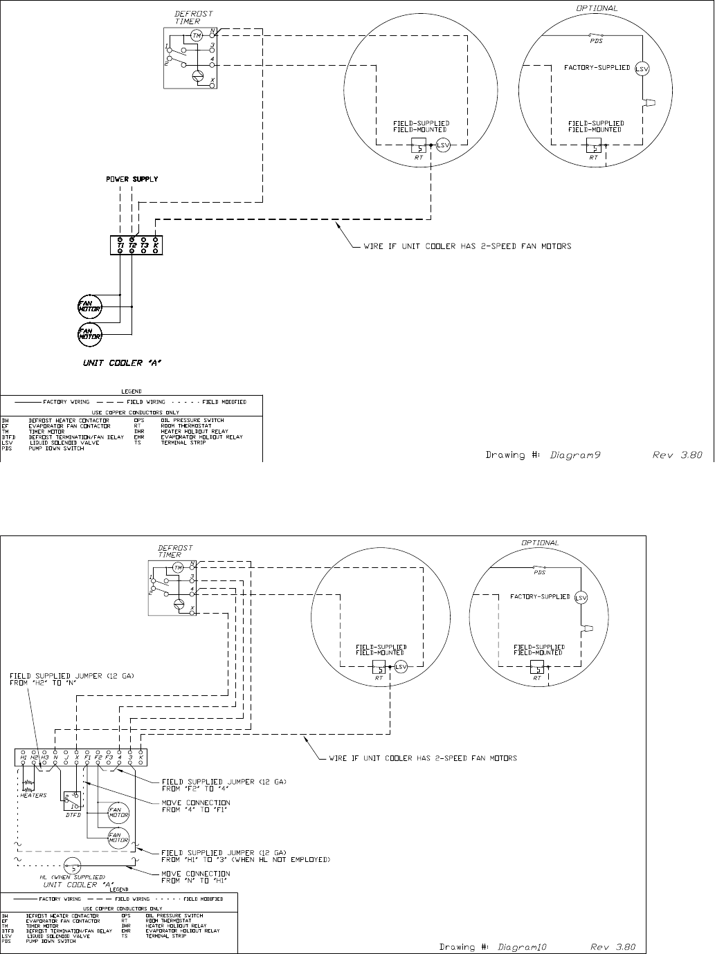
32
Diagram 9. Typical Wiring Diagram for Single Evaporator with and without Defrost Timer
Diagram 10. Typical Wiring Diagram for Single Evaporator with Defrost Timer Only
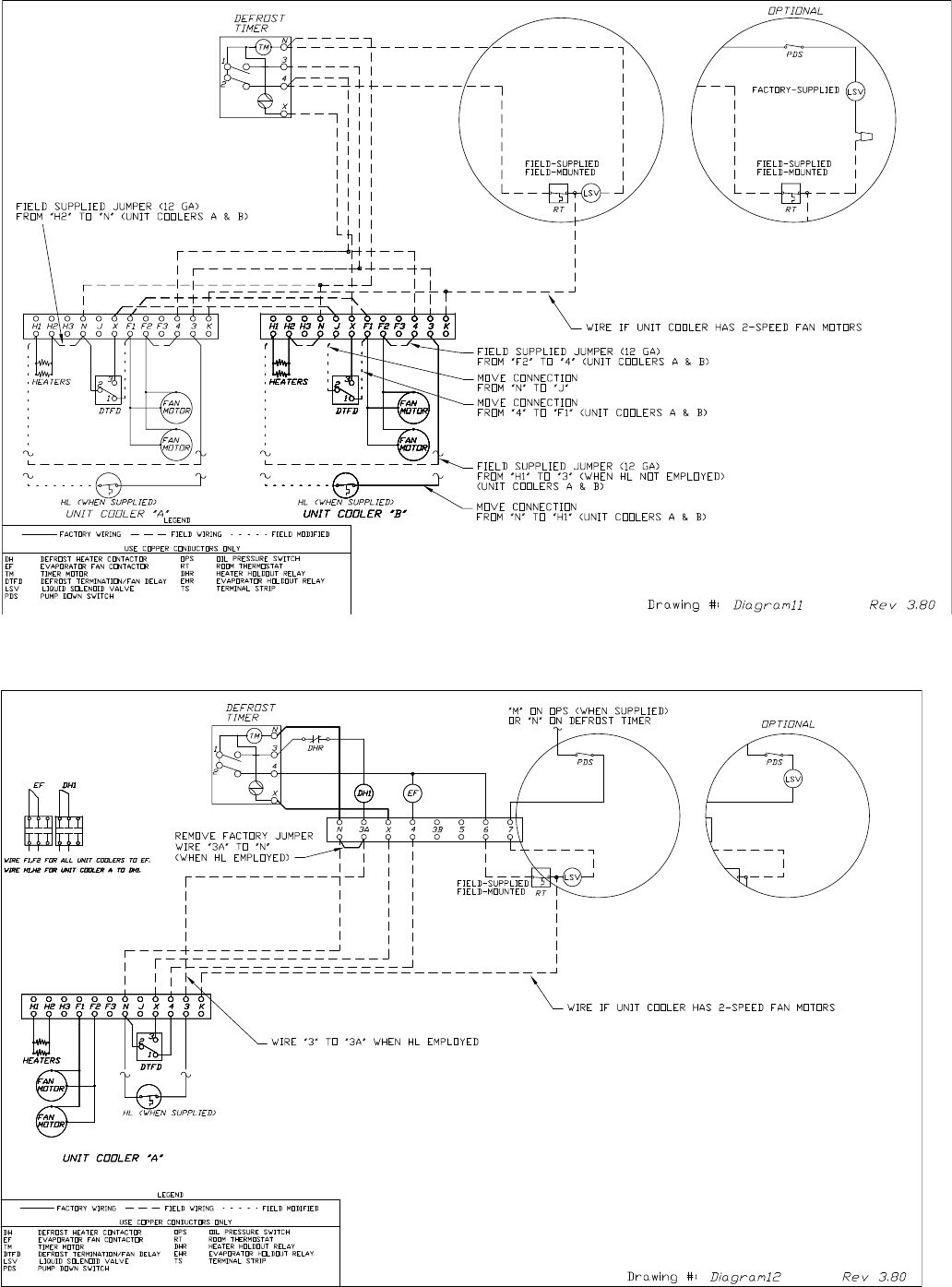
33
Diagram 11. Typical Wiring Diagram for Multiple Evaporators with Defrost Timer Only
Diagram 12. Typical Wiring Diagram for Single Evaporator / Single Phase Defrost and Evaporator Fan Contactors
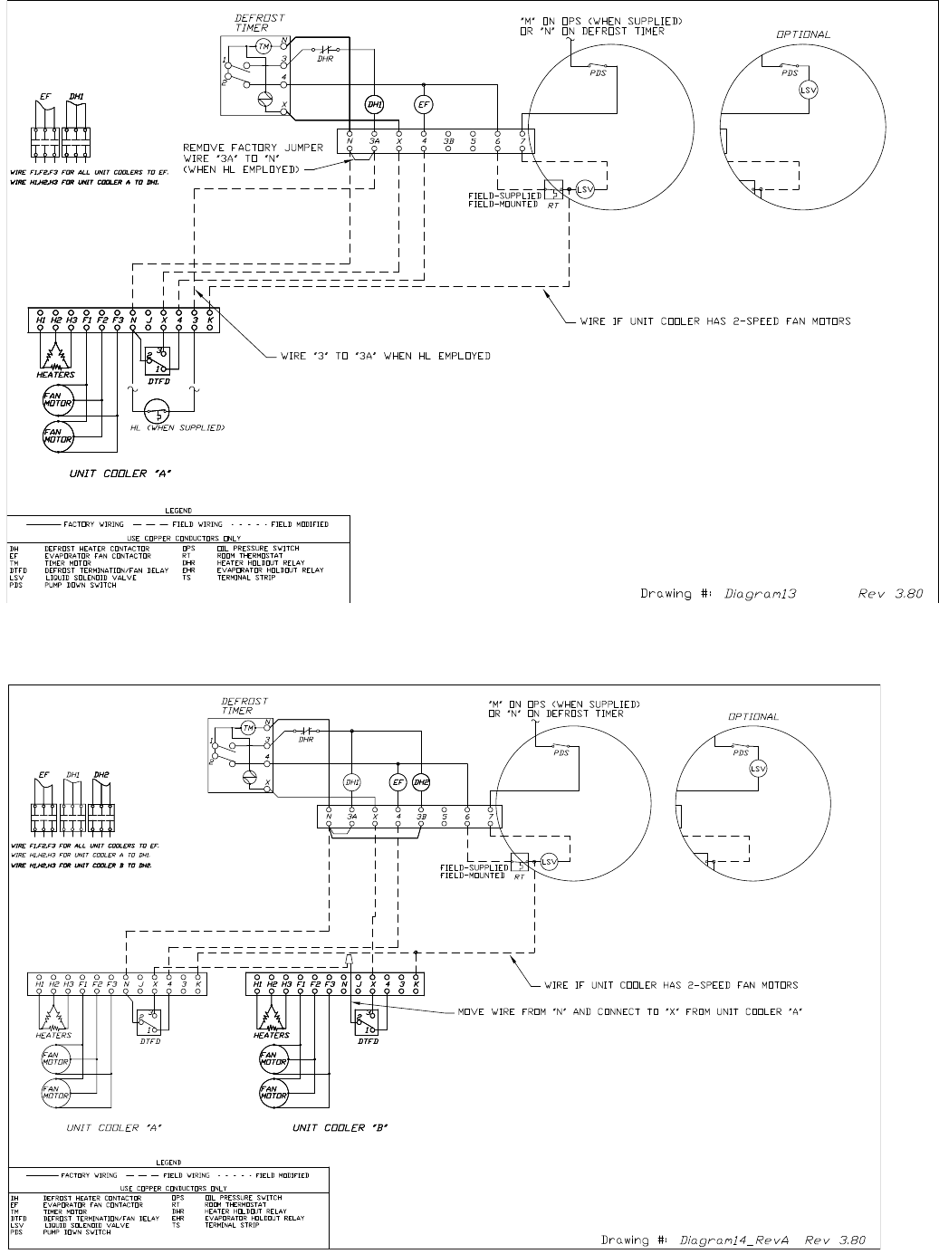
34
Diagram 13. Typical Wiring Diagram for Single Evaporator Defrost and Evaporator Fan Contactors
Diagram 14. Typical Wiring Diagram for Multiple Evaporators with Evaporator Fan Contactors/without
Heater Limit Defrost
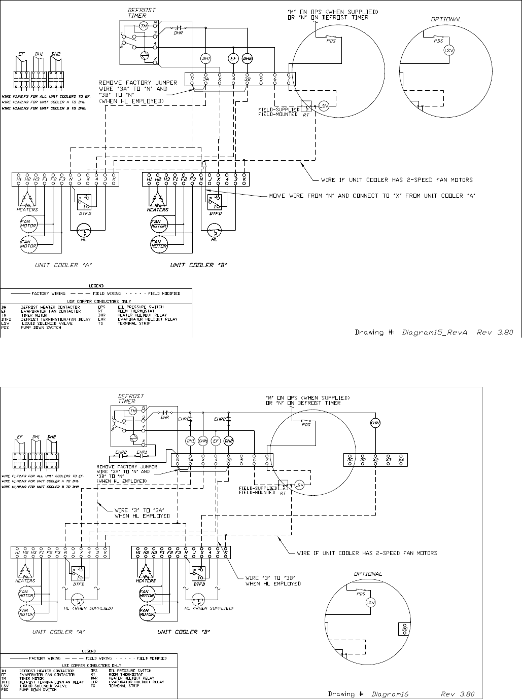
35
Diagram 16. Typical Wiring Diagram for Multiple Evaporators Defrost and Evaporator Fan Contactors with
Unit Cooler Holdout Relay
Diagram 15. Typical Wiring Diagram for Multiple Evaporators with Heater Limit Defrost and Evaporator
Fan Contactors

Since product improvement is a continuing eort, we reserve the right to make changes in
specications without notice.
CLIMATE
CONTROL
Commercial Refrigeration Parts
The name behind the brands you trust.
™
H-IM-CU-0223
