JANUARY 2020
www.gastite.com
DESIGN AND INSTALLATION GUIDE
Commercial I Industrial I Residential
FLEXIBLE GAS PIPING
SECTION 1: INTRODUCTION / JANUARY 2020
Important Lightning Safety Warning
1
PROPERLY BONDING
and grounding the
Corrugated Stainless Steel Tubing (CSST) system
may reduce the risk of damage and fire from a lightning
strike. Lightning is a highly destructive force. Even a
nearby lightning strike that does not strike a structure
directly can cause systems in the structure to become
electrically energized. Differences in potential between
systems may cause the charge to arc between systems.
Such arcing can cause damage to CSST, including holes.
Bonding and grounding should reduce the risk of arcing
and related damage. The building owner should confirm
that a qualified contractor has properly bonded the
CSST gas system to the grounding electrode system of
the premises. Refer to Section 4.10 Electrical Bonding/
Grounding in the Gastite
®
Design & Installation Guide
for details on bonding & grounding CSST.
2
ALL OWNERS
should consult a lightning safety
consultant to determine whether installation of a light-
ning protection system would be required to achieve
sufficient protection for all building components from
lightning. Factors to consider include whether the area
is prone to lightning. Areas with high lightning risk in
-
clude but are not limited to: Alabama, Arkansas, Florida,
Georgia, Illinois, Indiana, Iowa, Kentucky, Louisiana,
Maryland, Michigan, Mississippi, Missouri, New Mexi-
co, North Carolina, Ohio, Oklahoma, Pennsylvania, South
Carolina, Tennessee, Texas, Virginia and West Virginia.
One currently available source of information regard-
ing areas more prone to lighting than others is the flash
density map provided by the National Weather Service
which can be found at http://www.lightningsafety.noaa.
gov/lightning_map.htm. Lightning protection systems
are beyond the scope of this manual and installation
guidelines, but are covered by National Fire Protection
Association, NFPA 780, the Standard for the Installation
of Lightning Protection Systems, and other standards.
3
THE OWNER should confirm with the local
gas supply utility company that a suitable dielectric
union is installed at the service entry of the structure
between underground metallic piping and the gas
pipes going into the building as required by code.
LIGHTNING SAFETY WARNING
4
NATIONAL ELECTRIC CODE (NEC), Sec-
tion 250.104b, states that “bonding all piping and metal
air ducts within the premises will provide additional
safety.” Gastite recommends that all continuous metallic
systems be bonded and grounded. The owner should
confirm with an electrical or construction specialist
that each continuous metallic system in a structure has
been bonded and grounded by an electrical professional
in accordance with local building codes. This should
include, but is not limited to metallic chimney liners,
metallic appliance vents, metallic ducting and piping,
electrical cables, and structural steel.
5
DIRECT CONTACT
between continous
metallic systems and Gastite
®
yellow CSST is prohibited.
Maintain as much isolation/separation as reasonably possible
when planning and installing gas piping from other
continuous metalllic systems. Refer to sec. 4.3
Routing, in the Gastite
®
D&I Guide for installation
techniques. Consult local building codes as to required
separations for CSST from such continuous metallic systems
including metallic chimney liners, metallic appliance vents,
metallic ducting and piping, and insulated or jacketed
electrical wiring and cables. See for instance the Indiana
Residential Code, section 675 IAC 14-4.3-155.5 Section
G2411.1; gas pipe bonding.
6
LOCAL BUILDING CODES are controlling,
however, as a general practice, fuel gas piping, including
CSST, should not be installed within a chase or enclosure
that houses a metallic chimney liner or appliance vent
that protrudes through the roof. In the event such an
installation of Gastite
®
yellow CSST is necessary and conforms
to local building codes, the metallic chimney liner or vent must
be bonded and grounded by a qualified electrical professional,
and a separation distance, as specifically permitted by the
applicable local building code between the CSST and
the metallic chimney liner or vent, is required. Physical
contact between CSST and the metallic chimney liner
and/or vent is prohibited. If this physical separation
cannot be specifically identified in the local building
code and achieved or any local building code require-
ments cannot be met along the entire length, then
rerouting of the CSST is required unless such installation
is specifically permitted by the local building inspector.
© 2013, Gastite Division, Titeflex Corporation
GENERAL 1/20/13
www.gastite.com
INSTALLER INFORMATION & UPDATES
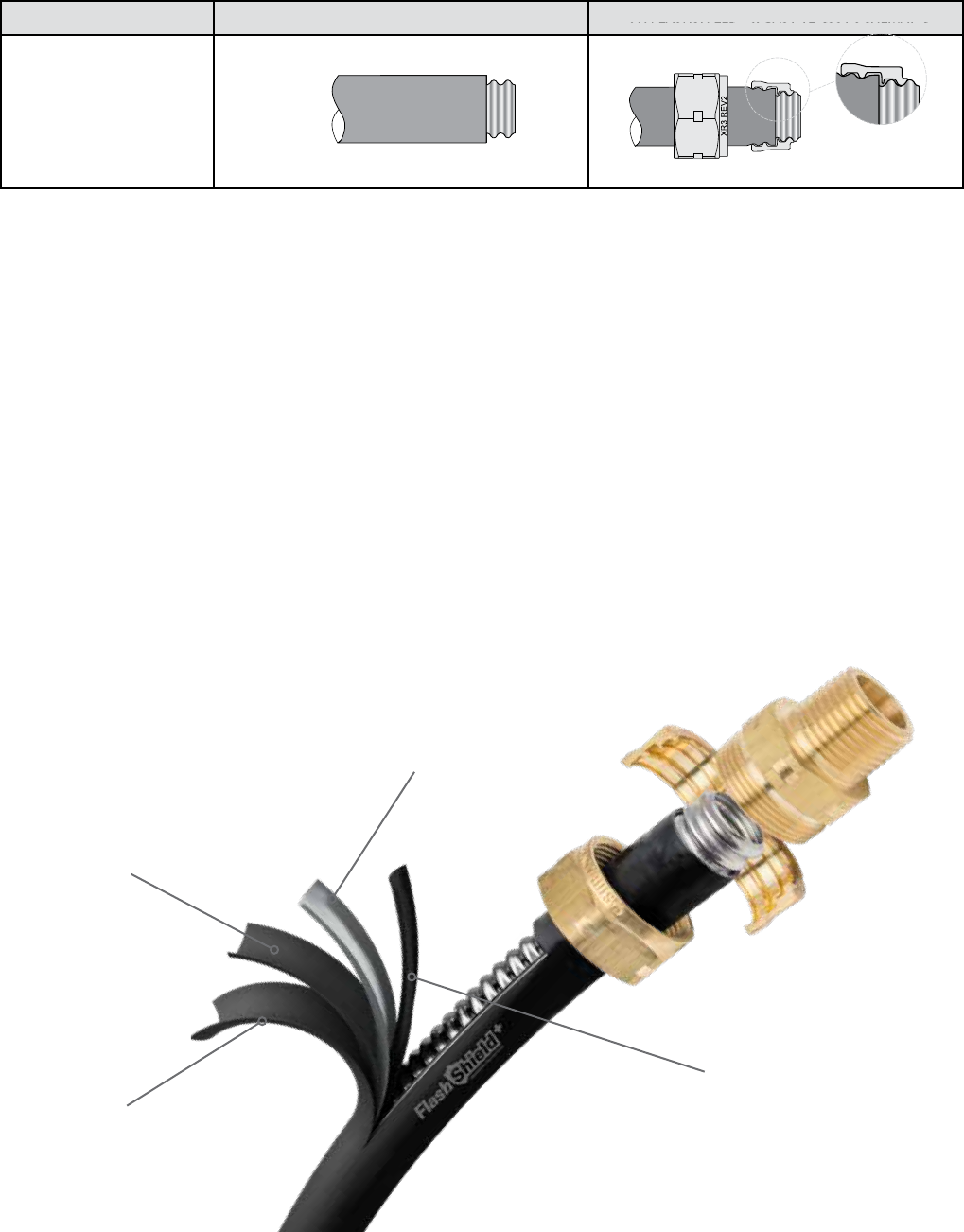
1) e XR3-series fitting is designed to work on Gastite® and FlashShield+™ CSSTs. However, CSST end-prep varies
by CSST product type. Reference the chart below for proper CSST end-prep and bushing placement for the product
you have selected.
PRODUCT CSST END-PREP BUSHING PLACEMENT
One-Step
End-Prep
FlashShield+™
or Gastite
®
CSST
2) Licensed Installers Only. Every installer of FlashShield
+
or Gastite must first meet all applicable qualifications in
accordance with state and/or local requirements as established by the administrative authorities that enforce the
plumbing or mechanical codes where gas piping is installed.
3) Qualified Installers Only. In addition to be licensed in the jurisdiction, FlashShield
+
or Gastite corrugated stainless
steel tubing (CSST) flexible gas piping material must only be installed by an installer who has been successfully
trained through the FlashShield
+
and Gastite® training program.
4) Check for Updates. Installers should check with their local distributor or at www.gastite.com for technical bulletins
or updated Design & Installation Guides for FlashShield
+
or Gastite every year.
5) Proper Installation. Sound engineering principles and practices must be exercised for the proper design of fuel gas
piping systems, in addition to compliance with local codes. e installation instructions and procedures contained
in this Design & Installation Guide must be strictly followed in order to provide a safe and effective flexible fuel gas
piping system or system modification. All installations must pass inspections by the local official having authority
prior to having the gas service turned on. All requirements of the local natural gas utility or propane supplier must
also be met.
High Tensile Polyester
Electrically Insulative
Polymer
Metallic Shield
Semi-conductive
Polymer
FLASHSHIELD+™

GASTITE DIVISION, TITEFLEX CORPORATION / 1116 Vaughn Parkway / Portland, TN 37148
800.662.0208 / www.gastite.com / [email protected]
iv
TABLE OF CONTENTS / JANUARY 2020
SECTION 1.0 INTRODUCTION
1.1 GENERAL USER WARNINGS .............................................................................................................................2
1.2 LIMITATIONS OF THE GUIDELINES .................................................................................................................. 5
1.3 STANDARDS, LISTINGS AND CODES ................................................................................................................ 5
SECTION 2.0 SYSTEM DESCRIPTIONS & COMPONENTS
2.1 SYSTEM DESCRIPTIONS .................................................................................................................................... 6
2.1.1 GAST I T E
®
SYSTEM DESCRIPTION ..................................................................................................................................... 6
2.1.2 FLASHSHIELD+ SYSTEM DESCRIPTION ............................................................................................................................ 7
2.2 COMPONENTS .................................................................................................................................................. 8
2.2.1 CORRUGATED STAINLESS STEEL TUBING ....................................................................................................................8–9
2.2.2 FITTINGS ..................................................................................................................................................................10 –11
2.2.3 MANIFOLDS .................................................................................................................................................................. 12
2.2.4 MODULAR STUB SYSTEM ............................................................................................................................................. 12
2.2.5 MOUNTING HARDWARE ............................................................................................................................................... 13
2.2.6 PIPE SUPPORT SYSTEM .................................................................................................................................................. 13
2.2.7 STRIKE PROTECTION ..................................................................................................................................................... 14
2.2.8 SHUT-OFF VALVES AND QUICK CONNECTS ................................................................................................................. 14
2.2.9 GASTITE ACCESSORIES ................................................................................................................................................. 15
2.2.10 BONDING CLAMPS ...................................................................................................................................................... 15
2.2.11 SYSTEM IDENTIFICATION............................................................................................................................................. 15
2.2.12 REGULATORS ............................................................................................................................................................... 16
SECTION 3.0 SYSTEM CONFIGURATION
3.1 CONFIGURATION............................................................................................................................................ 18
3.1.1 I NTRODUCTI O N ............................................................................................................................................................. 18
3.1.2 SYSTEM REQUIREMENTS .............................................................................................................................................. 18
3.1.3 REFERENCE DATA FOR PROPER SYSTEM SIZING ............................................................................................................ 18
3.1.4 DETERMINING SYSTEM LAYOUT ............................................................................................................................. 19–20
3.1.5 ALLOWABLE PRESSURE DROP ....................................................................................................................................... 21
3.1.6 SIZING METHODS .................................................................................................................................................... 21–22
3.1.7 MODIFYING AN EXISTING SYSTEM ............................................................................................................................... 22
3.2 SIZING PROCEDURES AND EXERCISES .......................................................................................................... 22
3.2.1 SIZING EXAMPLES ......................................................................................................................................................... 22
3.2.2 EXAMPLE 1: SERIES SYSTEM – 6"WC ..................................................................................................................... 23–24
3.2.3 EXAMPLE 2: PARALLEL SYSTEM – 6"WC ................................................................................................................ 25–26
3.2.4 EXAMPLE 3: PARALLEL SYSTEM – 12-14"WC ......................................................................................................... 27–28
3.2.5 EXAMPLE 4: DUAL PRESSURE SYSTEM – 2 PSI TRUNK AND 8"WC APPLIANCE RUNS ............................................ 29–30
3.2.6 EXAMPLE 5: TANKLESS SIZING SYSTEM ....................................................................................................................... 31
3.2.7 EXAMPLE 6: SERIES SYSTEM – 7"WC - HYBRID ............................................................................................................ 32
3.2.8 EXAMPLE 7: PARALLEL SYSTEM – 7"WC – HYBRID ................................................................................................ 34–35
3.2.9 EXAMPLE 8: SUMMATION METHOD FOR PARALLEL SYSTEM – 7"WC – HYBRID ................................................... 36–37
3.2.10 EXAMPLE 9: SUMMATION METHOD FOR SERIES SYSTEM – 6"WC ......................................................................38–40
3.2.11 EXAMPLE 10: COMMERCIAL ELEVATED PRESSURE SERIES SYSTEM – 2 PSI........................................................... 41– 42
3.2.12 EXAMPLE 11: COMMERCIAL HYBRID SYSTEM – 7"WC ........................................................................................ 43–45
SECTION 4.0 INSTALLATION PRACTICES
4.1 GENERAL PROVISIONS ................................................................................................................................... 47
4.2 FIELD FITTING ASSEMBLY PROCEDURE .........................................................................................................48
4.2.1 XR3 FITTING REV.2 TO FLASHSHIELD+ CSST OR GASTITE YELLOW CSST (WITH JACKET STRIPPING TOOL) ........... 48–49
4.2.2 XR3 FITTING REV.2 TO FLASHSHIELD+ CSST OR GASTITE YELLOW CSST (WITH UTILITY KNIFE) ........................... 50–51
4.2.4 OTHER ACCESSORY INSTALLATION .............................................................................................................................. 52
4.3 ROUTING ........................................................................................................................................................ 53
4.3.1 VERTICAL RUNS ............................................................................................................................................................ 53
4.3.2 HORIZONTAL RUNS ....................................................................................................................................................... 53
4.3.3 INSTALLATION CLEARANCE HOLES .............................................................................................................................. 53
4.3.4 CONCEALED FITTINGS .................................................................................................................................................. 54
4.3.5 MODIFICATIONS TO EXISTING SYSTEMS ...................................................................................................................... 54
4.3.6 OUTDOOR ..................................................................................................................................................................... 55

GASTITE DIVISION, TITEFLEX CORPORATION / 1116 Vaughn Parkway / Portland, TN 37148
800.662.0208 / www.gastite.com / [email protected]
v
TABLE OF CONTENTS / JANUARY 2020
4.3.7 FIRE RATED CONSTRUCTIONS ....................................................................................................................................... 55
4.3.8 ROUTING THROUGH MASONRY MATERIAL ................................................................................................................. 55
4.3.9 INSTALLATION WITHIN A CHASE .................................................................................................................................. 55
4.3.10 CLEARANCE FROM THE UNDERSIDE OF A ROOF DECK .............................................................................................. 55
4.4 STRIKE PROTECTION ...................................................................................................................................... 56
4.4.1 STRIKE PLATES ........................................................................................................................................................ 56–57
4.4.2 STEEL CONDUIT ............................................................................................................................................................ 58
4.5 METER ............................................................................................................................................................ 58
4.6 APPLIANCE ..................................................................................................................................................... 59
4.6.1 MOVEABLE APPLIANCE ................................................................................................................................................ 59
4.6.2 DIRECT CONNECTION – NON-MOVEABLE APPLIANCES ............................................................................................... 60
4.6.3 GAS CONVENIENCE OUTLET ........................................................................................................................................ 60
4.6.4 SPECIAL APPLICATIONS .......................................................................................................................................... 61– 64
4.7 MANIFOLD ..................................................................................................................................................... 65
4.8 PRESSURE REGULATOR .................................................................................................................................. 66
4.8.1 INTRODUCTION ............................................................................................................................................................ 66
4.8.2 SIZING INSTRUCTIONS ............................................................................................................................................ 66–67
4.8.3 INSTALL ATION .............................................................................................................................................................. 68
4.8.4 PERFORMANCE ............................................................................................................................................................. 69
4.8.5 REGULATOR OUTLET PRESSURE ADJUSTMENT ............................................................................................................. 69
4.8.6 OVER-PRESSURIZATION PROTECTION ........................................................................................................................... 69
4.9 UNDERGROUND INSTALLATIONS .................................................................................................................. 70
4.10 ELECTRICAL BONDING OF GASTITE/FLASHSHIELD+ CSST .......................................................................... 71
SECTION 5.0 INSPECTION, REPAIR & REPLACEMENT
5.1 MINIMUM INSPECTION REQUIREMENTS ...................................................................................................... 72
5.2 INSTALLATION CHECKLIST DESCRIPTION ...................................................................................................... 73
5.3 REPAIR OF DAMAGED CSST .......................................................................................................................... 74
5.3.1 DETERMINE DAMAGE ................................................................................................................................................... 74
5.3.2 METHOD OF REPAIR...................................................................................................................................................... 74
5.3.3 FLASHSHIELD+ JACKET REPAIR ..................................................................................................................................... 74
SECTION 6.0 PRESSURE/LEAKAGE TESTING
6.1 GENERAL GUIDELINES FOR PRESSURE TESTING ........................................................................................... 75
6.2 ELEVATED PRESSURE SYSTEMS ..................................................................................................................... 75
6.3 APPLIANCE CONNECTION LEAKAGE CHECK PROCEDURE...........................................................................76
SECTION 7.0 SIZING TABLES & PRESSURE DROP CHARTS
7.1 CSST CAPACITY TABLES—NATURAL GAS ............................................................................................... 77–80
7.2 CSST CAPACITY TABLES—NATURAL GAS—ELEVATED PRESSURE ......................................................... 81–82
7.3 CSST CAPACITY TABLES—PROPANE GAS ................................................................................................ 83–85
7.4 CSST CAPACITY TABLES—PROPANE GAS—ELEVATED PRESSURE ......................................................... 85–86
7.5 GASTITE AND FLASHSHIELD+ CSST PRESSURE DROP TABLES ................................................................ 87–88
7.6 IRON PIPE CAPACITY TABLES ........................................................................................................................ 91
7.7 IRON PIPE PRESSURE DROP TABLES .........................................................................................................92-95
7.8 REFERENCE DATA ........................................................................................................................................... 96
SECTION 8.0 DEFINITIONS ................................................................................ 97–98
SECTION 9.0 DIMENSIONAL & TECHNICAL REFERENCE DATA .............................99
9.1 GASTITE SPECIFICATION SHEET ................................................................................................................... 100
9.2 FLASHSHIELD+ SPECIFICATION SHEET ........................................................................................................ 101
SECTION 10.0 WARRANTY ................................................................................... 102

GASTITE DIVISION, TITEFLEX CORPORATION / 1116 Vaughn Parkway / Portland, TN 37148
800.662.0208 / www.gastite.com / [email protected]
2
SECTION 1: INTRODUCTION / JANUARY 2020
SECTION 1.0 INTRODUCTION
1.1 GENERAL USER WARNINGS
e installation of Gastite or FlashShield
+
Flexible Gas Piping must be performed by a qualified installer who has
successfully completed the Gastite/FlashShield
+
training program. Certification training is available through qualified
distributors, and at www.gastite.com. e installer must meet all qualifications and requirements to install gas piping as
required by the local administrative authority. Improper installation or operation of a Gastite or FlashShield
+
Flexible Gas
Piping system may result in fire, explosion or asphyxiation.
WARNING: is product can expose you to chemicals including Lead, and Nickel, which are known to the
State of California to cause cancer and birth defects or other reproductive harm. For more information go to
www.P65Warnings.ca.gov.
is document provides the user with general guidance when designing and installing fuel gas piping using Gastite®
or FlashShield
+
Flexible Gas Piping. is guideline must be used in conjunction with all applicable building standards
and codes. In the event that there is a conflict between this guideline and local code the more stringent requirement will
take precedence.
e use of fuel gas can be dangerous. Special attention must be given to the proper design, installation, testing and
application of the gas piping system. Sound engineering practices and principles must be exercised, as well as diligent
adherence to the proper installation procedures to ensure the safe operation of the piping system. All installed systems must
pass customary installation inspections by the local building official having authority prior to being placed into service.
Only the components provided or specified by Gastite as part of the Gastite/FlashShield
+
flexible fuel piping system are
to be used in the installation. Use of components from other flexible gas piping systems other than those specified as part
of the Gastite/FlashShield
+
system is prohibited and may result in poor system performance and serious bodily injury
or property damage. Where additions, repairs or replacements involve corrugated stainless steel tubing systems from
manufacturers other than Gastite Division, the systems should be joined using standard pipe fittings at the interface.
is manual cannot take into account all situations or locations in which Gastite/FlashShield
+
flexible gas piping will be
installed. Accordingly, installers should also take into account guidance provided by the National Fuel Gas Code, ANSI
Z223.1/NFPA-54, National Standard of Canada, Natural Gas and Propane Installation Code, B149.1, the Uniform
Plumbing Code, the International Code Series, the Federal Manufactured Home Construction and Safety Standards,
24 CFR Part 3280, the Manufactured Housing Construction and Safety Standards, ICC/ANSI 2.0 or the Standard
on Manufactured Housing, NFPA 501. Gastite Division shall have no responsibility for any misinterpretation of the
information contained in this guide or any improper installation or repair work or other deviation from procedures
recommended in this manual, whether pursuant to local building codes or engineering specifications or otherwise.
Gastite Division makes no representation or warranty, and nothing contained in this manual shall imply that this manual
contains the best or the only approved method for installing corrugated stainless steel piping systems or that this manual’s
contents are appropriate for all circumstances. In the event that there is a conflict between this guideline and local code the
more stringent requirement will take precedence. Performance of accessory devices, such as pressure regulators and shut
off valves should be reconfirmed by contacting the accessory device manufacturer and receiving the latest technical data on
sizing, installation and performance.

GASTITE DIVISION, TITEFLEX CORPORATION / 1116 Vaughn Parkway / Portland, TN 37148
800.662.0208 / www.gastite.com / [email protected]
3
SECTION 1: INTRODUCTION / JANUARY 2020
1.1 GENERAL USER WARNINGS (CONTINUED)
A Gastite/FlashShield
+
Flexible Gas Piping system offers advantages over other gas delivery systems because of its
corrugated design. In contrast to rigid steel pipe, Gastite/FlashShield
+
does not require intermediate joints in most
installations because the tubing is capable of being installed in one continuous run, reducing not only the total number
of joints, but also the potential for leaks at joints. Gastite/FlashShield
+
flexibility also affords more installation options
because an installer can avoid existing obstacles, and it eliminates the repetitive measuring, cutting, threading and joint
assembly that is common with installation of rigid steel piping systems. Gastite/FlashShield
+
’s flexibility offers even further
safety advantages in geographic areas that are prone to seismic activity because the tubing is able to move as the ground or
the structure shifts.
While Gastite/FlashShield
+
provides significant advantages over more rigid gas delivery systems, its flexible design may
make it more likely than steel pipe to be punctured by a nail or other sharp objects, or damaged by other extraordinary
forces such as lightning strike, depending on the circumstances.
Properly bonding and grounding the Corrugated Stainless Steel Tubing (CSST) system may reduce the risk of
damage and fire from a lightning strike. Lightning is a highly destructive force. Even a nearby lightning strike that
does not strike a structure directly can cause systems in the structure to become electrically energized. Differences
in potential between systems may cause the charge to arc between systems. Such arcing can cause damage to CSST,
including holes. Bonding and grounding should reduce the risk of arcing and related damage. e building owner should
confirm that a qualified contractor has properly bonded the CSST gas system to the grounding electrode system of the
premises. Refer to Section 4.10 Electrical Bonding/Grounding in the Gastite/FlashShield
+
Design & Installation Guide
for details on bonding & grounding CSST.
All owners should consult a lightning safety consultant to determine whether installation of a lightning protection system
would be required to achieve sufficient protection for all building components from lightning. Factors to consider include
whether the area is prone to lightning. Areas with high lightning risk include but are not limited to: Arkansas, Florida,
Georgia, Illinois, Indiana, Iowa, Kentucky, Louisiana, Maryland, Michigan, Mississippi, Missouri, New Mexico, North
Carolina, Ohio, Oklahoma, Pennsylvania, South Carolina, Tennessee, Texas and West Virginia. One currently available
source of information regarding areas more prone to lighting than others is the flash density map provided by the National
Weather Service which can be found at http://www.lightningsafety.noaa.gov/lightning_map.htm. Lightning protection
systems are beyond the scope of this manual and installation guidelines, but are covered by National Fire Protection
Association, NFPA 780, the Standard for the Installation of Lightning Protection Systems, and other standards. e owner
should confirm with the local gas supply utility company that a suitable dielectric union is installed at the service entry of
the structure between underground metallic piping and the gas pipes going into the building as required by code.
Section 250.104b of the National Electric Code (NEC) states that “bonding all piping and metal air ducts within
the premises will provide additional safety.” Gastite recommends that all continuous metallic systems be bonded and
grounded. e owner should confirm with an electrical or construction specialist that each continuous metallic system in a
structure has been bonded and grounded by an electrical professional in accordance with local building codes. is should
include, but is not limited to: metallic chimney liners, metallic appliance vents, metallic ducting and piping, electrical
cables, and structural steel.

GASTITE DIVISION, TITEFLEX CORPORATION / 1116 Vaughn Parkway / Portland, TN 37148
800.662.0208 / www.gastite.com / [email protected]
4
SECTION 1: INTRODUCTION / JANUARY 2020
1.1 GENERAL USER WARNINGS (CONTINUED)
Direct contact between electrically continuous metallic systems and Gastite yellow CSST is prohibited. Maintain as
much isolation/separation as reasonably possible when planning and installing gas piping from other continuous metallic
systems. Refer to Section 4.3 Routing, in the Gastite/FlashShield
+
D&I Guide for installation techniques. Consult local
building codes as to required separations for CSST from such continuous metallic systems including metallic chimney
liners, metallic appliance vents, metallic ducting and piping, and insulated or jacketed electrical wiring and cables. See for
instance the Indiana Residential Code, Section 675 IAC 14-4.3-155.5 Section G2411.1; gas pipe bonding.
Local building codes are controlling, however, as a general practice, fuel gas piping, including CSST, should not be
installed within a chase or enclosure that houses a metallic chimney liner or appliance vent that protrudes through the roof.
In the event such an installation of Gastite yellow CSST is necessary and conforms to local building codes, the metallic
chimney liner or vent must be bonded and grounded by a qualified electrical professional, and a separation distance, as
specifically permitted by the applicable local building code between the CSST and the metallic chimney liner or vent,
is required. Physical contact between CSST and the metallic chimney liner and/or vent is prohibited. If this physical
separation cannot be specifically identified in the local building code and achieved or any local building code requirements
cannot be met along the entire length, then rerouting of the CSST is required unless such installation is specifically
permitted by the local building inspector.
Corrosive substances: Steel piping, brass fittings and valves can be corroded by various chemical substances which may be
present on a jobsite or in a structure. Chlorinated compounds can cause pitting and crevice corrosion of stainless steel. Am-
monia and other nitrogenous compounds can cause stress corrosion cracking of brass. FlashShield
+
's jacket system provides
protection from many harmful substances and should remain intact over the lengths of stainless steel tubing to maintain
this protection.
While not exhaustive, the list below provides guidance of substances which should not come into contact with stainless
steel or brass. If there is a question about the suitability of a certain substance in the environment, the user should refer to
the ingredient list or contact the manufacturer.
Chlorinated compounds (chloride, chlorite, chloric, chlorous, chloro, chlorate):
• Some household soaps*
• Masonry cleaner (Muriatic acid)
• Soldering flux
• Bleach
• Pool chemicals
• Ice melt
• Soils, soil water, concrete
Ammonia and ammonium containing compounds:
• Household cleaners
• Fertilizers
Nitrogenous compounds, such as amines:
• Herbicides, pesticides, fungicides, insecticides
* Some household soaps that contractors have used to make leak check solution may contain chlorides which can cause
corrosion to metallic components. Only use leak test solution which are labeled as non-corrosive, for gas piping systems.
Caution: Tube ends are sharp, use care when handling.

GASTITE DIVISION, TITEFLEX CORPORATION / 1116 Vaughn Parkway / Portland, TN 37148
800.662.0208 / www.gastite.com / [email protected]
5
SECTION 1: INTRODUCTION / JANUARY 2020
1.2 LIMITATIONS OF THE GUIDELINES
is document is intended to aid the professional gas installer in the design, installation and testing of fuel gas piping
systems using corrugated stainless steel tubing (CSST) for residential housing, commercial and industrial buildings.
It would be impossible for this guideline to anticipate and cover every possible variation in building configurations,
construction styles, appliance loads and code restrictions. erefore, there will be applications that will not be covered by
this guideline. For applications that go beyond the scope of this guideline, the installer should exercise sound engineering
principles and practices and/or contact Gastite for engineering assistance.
e techniques outlined within this guideline are recommended practice for generic applications. ese practices must be
reviewed for compliance with all applicable local fuel gas and building codes. In the event that there is a conflict between
this guide and local code, the more stringent requirement will take precedence.
Using components from other flexible gas piping systems other than those specified as part of the Gastite/FlashShield
+
system is prohibited and may result in poor system performance and serious bodily injury or property damage. Additional
information pertaining to gas piping systems is available from your local gas utility or propane supplier. Please visit the
Gastite web site at www.gastite.com for additional updates and technical bulletins.
1.3 STANDARDS, LISTINGS AND CODES
e Gastite/FlashShield
+
corrugated stainless steel tubing system complies with the following standards, listings and
model codes.
STANDARDS
ANSI LC1/CSA 6.26 – Fuel Gas Piping Systems Using Corrugated Stainless Steel Tubing (CSST)
ANSI LC1/CSA 6.26 – 25 PSI Operating Pressure Rating
ANSI LC1/CSA 6.26 Sec. 5.16– Arc Resistant (AR) Jacket Rating (FlashShield
+
)
ICC-ES PMG LC1027 – Protective Jacketed CSST, A Minimum 36-Coulomb Charge Transfer (FlashShield
+
)
LISTINGS
• CSA – CSA International – Certificate No. 2728525
• ICC – International Code Council – Evaluation Report Number PMG-1019, PMG-1155
• IAPMO – International Association of Plumbing and Mechanical Officials – File Number 3250, Report #0239
CODE COMPLIANCE
• ICC – International Code Series
• Canada – National Gas & Propane Installation Code B149.1
• NFPA – National Fuel Gas Code (NFPA 54)
• UMC – Uniform Mechanical Code
• UPC – Uniform Plumbing Code
While every effort has been made to prepare this document in accordance with all regional model codes in effect at its
printing, Gastite cannot guarantee that the local administrative authority will accept the most recent version of these
codes. It is the ultimate responsibility of the installer to determine suitability and acceptance of any building component
including gas piping. Gastite assumes no responsibility for labor or material for installations made without prior
determination of local code authority acceptance.

GASTITE DIVISION, TITEFLEX CORPORATION / 1116 Vaughn Parkway / Portland, TN 37148
800.662.0208 / www.gastite.com / [email protected]
6
SECTION 2: SYSTEM DESCRIPTIONS & COMPONENTS / JANUARY 2020
SECTION 2.0 SYSTEM DESCRIPTIONS & COMPONENTS
2.1 SYSTEM DESCRIPTIONS
2.1.1 GASTITE
®
SYSTEM DESCRIPTION
a) e Gastite Flexible Gas Piping System has been tested in accordance with the American National Standard for Fuel Gas
Systems Using Corrugated Stainless Steel Tubing, ANSI LC1/CSA 6.26. is standard lists performance requirements
for certification of CSST systems for use with all recognized fuel gases, including Natural Gas and Propane.
• System uses corrugated stainless steel tubing (CSST) made of type 304 alloy, ASTM A240.
• An annealing process tempers the steel giving it added flexibility and ease of bending.
• Gastite Flexible Gas Piping is suitable for use with elevated pressure systems. e ANSI LC1 standard rates CSST for use at
pressures up to 25 PSI.
b) e tubing is connected using XR3 mechanical brass fittings designed specifically for Gastite CSST.
• e self-flaring fitting creates a one step, reusable, metal on metal seal.
• Corrosion resistant brass fittings incorporate the Gastite patented Jacket-Lock™ feature. e polymer jacket is clamped by the
fitting thereby minimizing the risk of corrosives contacting the CSST.
• Gastite fittings have standard NPT threads and may be used in combination with all approved fuel gas piping materials with
the pipe threads as the interface. System components such as manifolds, tees and stub-outs may be fabricated from other
approved materials to be used with Gastite® flexible gas piping.
c) e polymer jacket is extruded over the stainless steel tubing creating a flexible, protective covering. e jacket is an
added feature of the tubing and does not affect the flaring/sealing process.
• e jacket provides an electrically insulative cover over the CSST gas vessel.
• e jacket is engineered with thermal and UV resistant material making it suitable for outdoor use.
• e polymer jacket creates a smooth outside surface; this surface greatly aids in pulling the tube through tight building
spaces.
• e polymer jacket blend contains flame and smoke additives making it ASTM E84 and CAN/ULC-S102.2 25/50
compliant.
d) e corrugated stainless steel tubing system has a number of essential hardware and design differences from conventional
gas piping using rigid steel pipe and copper tubing. ese differences are described as follows:
• In many applications, the tubing is sized for individual gas appliance loads and is, therefore, usually small in diameter. e
tubing may also be installed in a parallel fashion from a central distribution manifold rather than a series layout
commonly used for rigid pipe systems.
• Corrugated Stainless Steel Tubing is pulled through the structure similar in fashion to electrical wiring and therefore
requires different handling and installation techniques than rigid pipe.
• Rigid termination of the tube ends is required.
• Flexibility and strike plates protect the CSST allowing it to be run in concealed spaces.

GASTITE DIVISION, TITEFLEX CORPORATION / 1116 Vaughn Parkway / Portland, TN 37148
800.662.0208 / www.gastite.com / [email protected]
7
SECTION 2: SYSTEM DESCRIPTIONS & COMPONENTS / JANUARY 2020
2.1.2 FLASHSHIELD+™ SYSTEM DESCRIPTION
a) e FlashShield
+
Flexible Gas Piping System has been tested in accordance with the American National Standard for
Fuel Gas Systems Using Corrugated Stainless Steel Tubing, ANSI LC1/CSA 6.26. is standard lists performance
requirements for certification of CSST systems for use with all recognized fuel gases, including Natural Gas and
Propane. FlashShield+™ is also tested and listed in accordance with ICC-ES PMG LC1027, listing criteria for protective
jacketed CSST.
• Electrically insulative polymer cover.
• Metallically shielded CSST.
• Shield is electrically continuous through fitting joints (Arc-Trap™).
• System uses corrugated stainless steel tubing (CSST) made of type 304 alloy, ASTM A240.
• e ANSI LC1 standard rates
FlashShield
+
for use at pressures up to 25 PSI.
• FlashShield+
™ is listed to the Arc Resistant (AR) jacket tests of ANSI LCI/CSA 6.26 and ICC-ES PMG LC1027
b) e tubing is connected using XR3 REV2-series mechanical brass fittings.
• e self-flaring fitting creates a one step, reusable, metal on metal seal.
• Fitting creates metal shield-to-fitting electrical connectivity (Arc-Trap™).
• e jacket is clamped by the fitting (Jacket-Lock™) thereby minimizing the risk of corrosives contacting the CSST.
• Fittings have standard NPT threads and may be used in combination with all approved fuel gas piping materials
with the pipe threads as the interface. System components such as manifolds, tees and stubouts may be fabricated
from other approved materials to be used with
FlashShield
+
flexible gas piping.
c) e metallic laminant jacket is fabricated over the stainless steel tubing to provide a flexible, protective covering.
e jacket is an added feature of the tubing and does not affect the flaring/sealing process.
• Integrated metallic shield between insulative polymer outer cover and semi-conductive poly inner layer.
• e jacket is engineered with thermal and UV resistant material making it suitable for outdoor use.
• e jacket provides a smooth outside surface; this surface greatly aids in pulling the tube through tight building spaces.
• e polymer jacket blend contains flame and smoke additives making it ASTM E84 and CAN/ULC-S102.2 25/50
compliant.
d) e corrugated stainless steel tubing system has a number of essential hardware and design differences from
conventional gas piping using rigid steel pipe and copper tubing. ese differences are described as follows:
• In many applications, the tubing is sized for individual gas appliance loads and is, therefore, usually small in diameter.
e tubing may also be installed in a parallel fashion from a central distribution manifold rather than a series layout
commonly used for rigid pipe systems.
• Corrugated Stainless Steel Tubing is pulled through the structure similar in fashion to electrical wiring and therefore requires
different handling and installation techniques than rigid pipe.
• Rigid termination of the tube ends is required.
• Flexibility and strike plates protect the CSST allowing it to be run in concealed spaces.

GASTITE DIVISION, TITEFLEX CORPORATION / 1116 Vaughn Parkway / Portland, TN 37148
800.662.0208 / www.gastite.com / [email protected]
8
SECTION 2: SYSTEM DESCRIPTIONS & COMPONENTS / JANUARY 2020
2.2 COMPONENTS
2.2.1 CORRUGATED STAINLESS STEEL TUBING
GASTITE
®
CORRUGATED STAINLESS STEEL TUBING (CSST)
CSST
Part No. Description Pkg. Qty.
S93-6A4-250 3/8" Corrugated Stainless Steel Tubing 250 Ft/Coil
S93-6A4-50* 50 Ft/Box
S93-6A4-125 125 Ft/Coil
S93-6A4-500 500 Ft/Coil
S93-6A4-1000 1000 Ft/Coil
S93-8A4-250 1/2" Corrugated Stainless Steel Tubing 250 Ft/Coil
S93-8A4-25 25 Ft/Coil
S93-8A4-50* 50 Ft/Box
S93-8A4-125 125 Ft/Coil
S93-8A4-500 500 Ft/Coil
S93-8A4-1000 1000 Ft/Coil
S93-8A4-1500 1500 Ft/Coil
S93-11B4-250 3/4" Corrugated Stainless Steel Tubing 250 Ft/Coil
S93-11B4-25 25 Ft/Coil
S93-11B4-50* 50 Ft/Box
S93-11B4-125 125 Ft/Coil
S93-11B4-500 500 Ft/Coil
S93-11B4-1000 1000 Ft/Coil
S93-16A4-150 1" Corrugated Stainless Steel Tubing 150 Ft/Coil
S93-16A4-50* 50 Ft/Box
S93-16A4-75 75 Ft/Coil
S93-16A4-300 300 Ft/Coil
S93-16A4-500 500 Ft/Coil
S93-20A4-150 1-1/4" Corrugated Stainless Steel Tubing 150 Ft/Coil
S93-20A4-50 50 Ft/Coil
S93-20A4-75 75 Ft/Coil
S93-20A4-300 300 Ft/Coil
S93-24A4-150 1-1/2" Corrugated Stainless Steel Tubing 150 Ft/Coil
S93-24A4-50 50 Ft/Coil
S93-24A4-75 75 Ft/Coil
S93-24A4-300 300 Ft/Coil
S93-32A4-150 2" Corrugated Stainless Steel Tubing 150 Ft/Coil
S93-32A4-50 50 Ft/Coil
S93-32A4-75 75 Ft/Coil
S93-32A4-300 300 Ft/Coil
* Packaged in box. Please contact Gastite Customer Service for custom lengths.
APPLICATION
• CSST flexible gas piping supplies natural gas or liquefied petroleum gas to appliances.
MATERIAL / SPECIFICATIONS
• Tubing: ASTM A240 Type 304, Stainless Steel.
• Jacket: Electrically insulative and UV resistant polymer, complying with requirements of ASTM E84 and CAN/ULC-S102.2 25/50.
FEATURES AND BENEFITS
• Flexibility and durability allows for simple routing through complex building structures and designs.
• Pre-marked by the foot for easy measuring and installation.
• Minimum tubing wall thickness of .01" on all sizes is more robust than other brands of CSST.
• Annealed 304 stainless steel makes tubing more flexible than brands not heat-treated.

GASTITE DIVISION, TITEFLEX CORPORATION / 1116 Vaughn Parkway / Portland, TN 37148
800.662.0208 / www.gastite.com / [email protected]
9
SECTION 2: SYSTEM DESCRIPTIONS & COMPONENTS / JANUARY 2020
2.2.1 CORRUGATED STAINLESS STEEL TUBING
FSP-series
CSST
FLASHSHIELD+ CORRUGATED STAINLESS STEEL TUBING (CSST)
Part No. Description Pkg. Qty.
FSP-8-250 1/2" FlashShield+ Corrugated Stainless Steel Tubing 250 Ft/Coil
FSP-8-25-5* 25 Ft/Coil (5 Coils/Box)
FSP-8-50 50 Ft/Coil
FSP-8-125 125 Ft/Coil
FSP-8-500 500 Ft/Coil
FSP-8-1000 1000 Ft/Coil
FSP-8-1500 1500 Ft/Coil
FSP-11-250 3/4" FlashShield+ Corrugated Stainless Steel Tubing 250 Ft/Coil
FSP-11-25-5* 25 Ft/Coil (5 Coils/Box)
FSP-11-50 50 Ft/Coil
FSP-11-125 125 Ft/Coil
FSP-11-500 500 Ft/Coil
FSP-11-1000 1000 Ft/Coil
FSP-16-150 1" FlashShield+ Corrugated Stainless Steel Tubing 150 Ft/Coil
FSP-16-25-5* 25 Ft/Coil (5 Coils/Box)
FSP-16-50* 50 Ft/Coil
FSP-16-75 75 Ft/Coil
FSP-16-300 300 Ft/Coil
FSP-16-500 500 Ft/Coil
FSP-20-150 1-1/4" FlashShield+ Corrugated Stainless Steel Tubing 150 Ft/Coil
FSP-20-50 50 Ft/Coil
FSP-20-75 75 Ft/Coil
FSP-20-300 300 Ft/Coil
FSP-24-150 1-1/2"
FlashShield+ Corrugated Stainless Steel Tubing 150 Ft/Coil
FSP-24-50 50 Ft/Coil
FSP-24-75 75 Ft/Coil
FSP-32-150 2"
FlashShield+ Corrugated Stainless Steel Tubing 150 Ft/Coil
FSP-32-50 50 Ft/Coil
FSP-32-75 75 Ft/Coil
*Packaged in a box. Please contact Gastite Customer Service for custom lengths.
APPLICATION
• CSST flexible gas piping supplies natural gas or liquefied petroleum gas to appliances.
MATERIAL / SPECIFICATIONS
• Tubing: ASTM A240 Type 304 Stainless Steel.
• Jacket: Electrically insulative and UV resistant polymer, complying with requirements of ASTM E84 and CAN/ULC-S102.2 25/50.
• Protective jacket system, complies with ICC-ES PMG LC1027
FEATURES AND BENEFITS
• Electrically insulative polymer cover.
• Metallically shielded CSST.
• Protective shield is electrically continuous through fitting joints (Arc-Trap™).
• Metal shield layer dissipates and conducts electricity.
• No manufacturer required bonding.
• Flexibility means quick and easy installations. FlashShield+™ installs 30-70% faster than traditional piping methods.
• Pre-marked by the foot, there’s no measuring, rigid pipe cutting or threading. is means less waste and fewer fittings.
• 75% fewer fittings in the average installation means a safer system, less leak potential and reduced callbacks.
• FlashShield+™ CSST is lightweight—250 feet of 1/2" CSST weighs approx. 50 lbs and can be easily transported and handled on the job.
GASTITE DIVISION, TITEFLEX CORPORATION / 1116 Vaughn Parkway / Portland, TN 37148
800.662.0208 / www.gastite.com / [email protected]
10
SECTION 2: SYSTEM DESCRIPTIONS & COMPONENTS / JANUARY 2020
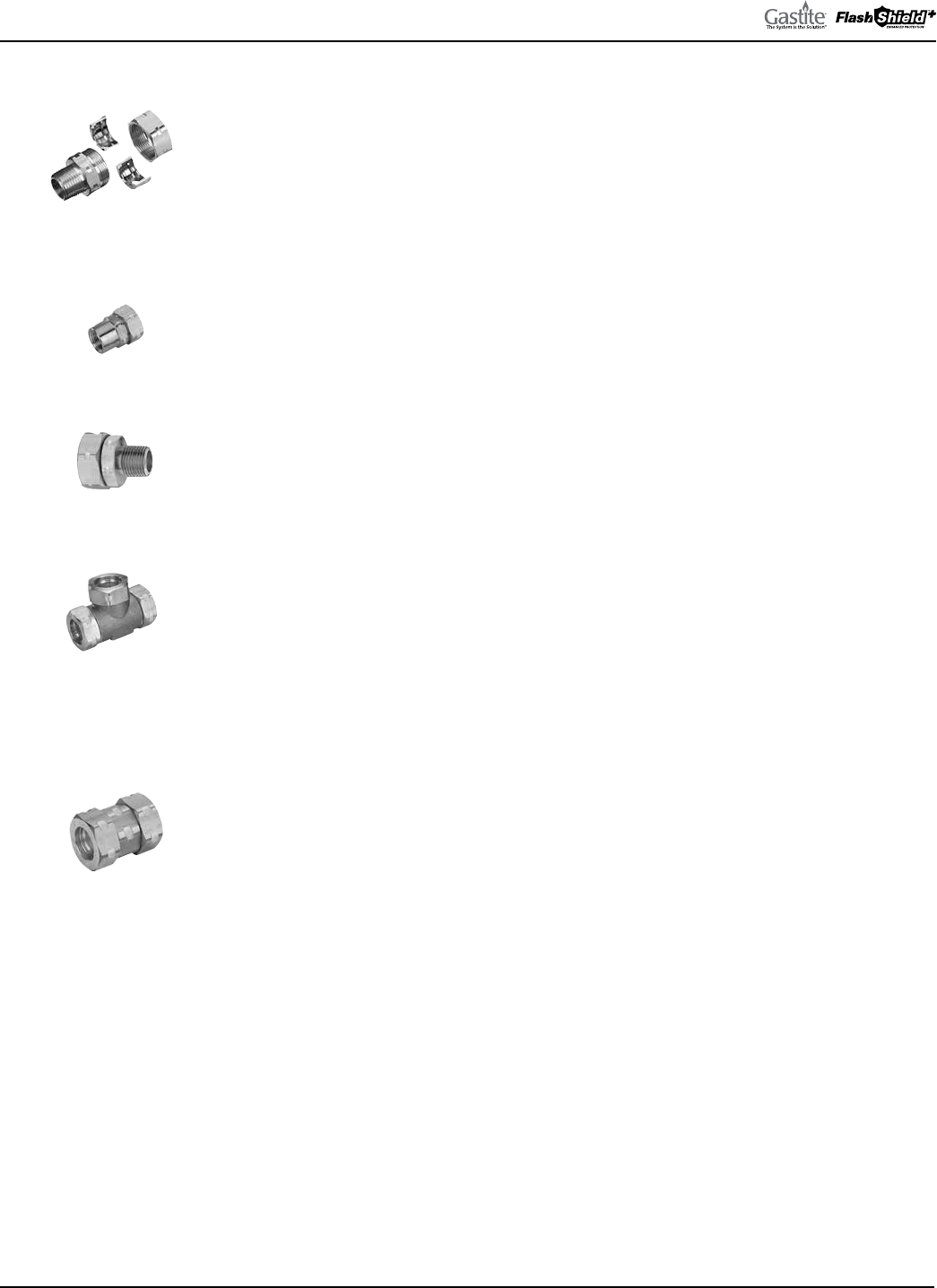
2.2.2 FITTINGS
XR2/XR3 SERIES STRAIGHT FITTING
(ADAPTER/NUT/BUSHING)
Straight Fitting
Part No. Description Pkg. Qty.
XR2FTG-6-24 3/8" Straight Fitting – 1/2" NPT 24/Box
XR3FTG-8-24 1/2" Straight Fitting – 1/2" NPT 24/Box
XR3FTG-11-24 3/4" Straight Fitting – 3/4" NPT 24/Box
XR3FTG-16-12 1" Straight Fitting – 1" NPT 12/Box
XR3FTG-20-6 1-1/4" Straight Fitting – 1-1/4" NPT 6/Box
XR3FTG-24-4 1-1/2" Straight Fitting – 1-1/2" NPT 4/Box
XR3FTG-32-4 2" Straight Fitting – 2" NPT 4/Box
XR3 SERIES STRAIGHT FEMALE FITTING (ADAPTER/NUT/BUSHING)
Straight Female
Fitting
Part No. Description Pkg. Qty.
XR3FTGFM-8-24 1/2" Straight Fitting – 1/2" Female NPT 24/Box
XR3FTGFM-11-8-24 3/4" Straight Fitting – 1/2" Female NPT 24/Box
XR3FTGFM-11-24 3/4" Straight Fitting – 3/4" Female NPT 24/Box
XR3 SERIES REDUCING FITTING (ADAPTER/NUT/BUSHING)
Reducing Fitting
Part No. Description Pkg. Qty.
XR3REDFTG-8-12-24 1/2" Straight Reducing Fitting – 3/4" NPT 24/Box
XR3REDFTG-11-8-24 3/4" Straight Reducing Fitting – 1/2" NPT 24/Box
XR3REDFTG-16-12-12 1" Straight Reducing Fitting – 3/4" NPT 12/Box
XR3 SERIES TEE FITTING
Tee Fitting
Tee
Run
Run
Part No. Description Pkg. Qty.
XR3T-8-12 1/2" Run x 1/2" Run x 1/2" Tee – Tee Fitting 12/Box
XR3T-11-12 3/4" Run x 3/4" Run x 3/4" Tee – Tee Fitting 12/Box
XR3T-16-6 1" Run x 1" Run x 1" Tee – Tee Fitting 6/Box
XR3T-11-8-8-6 3/4" Run x 1/2" Run x 1/2" Tee – Tee Fitting 6/Box
XR3T-11-11-8-6 3/4" Run x 3/4" Run x 1/2" Tee – Tee Fitting 6/Box
XR3T-16-11-8-6 1" Run x 3/4" Run x 1/2" Tee – Tee Fitting 6/Box
XR3T-16-11-11-6 1" Run x 3/4" Run x 3/4" Tee – Tee Fitting 6/Box
XR3T-16-16-8-6 1" Run x 1" Run x 1/2" Tee – Tee Fitting 6/Box
XR3T-16-16-11-6 1" Run x 1" Run x 3/4" Tee – Tee Fitting 6/Box
XR2/XR3 SERIES COUPLING FITTINGS
Coupling
Part No. Description Pkg. Qty.
XR2CPL-6-12 3/8" Coupling 12/Box
XR3CPL-8-12 1/2" Coupling 12/Box
XR3CPL-11-12 3/4" Coupling 12/Box
XR3CPL-16-6 1" Coupling 6/Box
XR3CPL-20-6 1-1/4" Coupling 6/Box
XR3CPL-24-4 1-1/2" Coupling 4/Box
XR3CPL-32-4 2" Coupling 4/Box
Note: Fitting Components available. Please contact Customer Service for pricing.
APPLICATION
• XR3 Fittings are used on both FlashShield+ black CSST and Gastite® yellow CSST.
• Straight Fittings connect the flexible gas tubing to gas supply, distribution manifolds or gas appliances.
• Tee Fittings create a branch line on tubing runs.
• Couplings allow for the splicing and additions to the flexible gas tubing.
MATERIAL / SPECIFICATIONS
• Fitting adapter, bushings and nut – Brass.
FEATURES AND BENEFITS
• Tool-less flare design; no special tools are required.
• Metal-to-metal seal, with no split rings, O-rings or gaskets.
• Self-guiding assembly to ensure a perfectly even flare.
• Exclusive, patented Jacket-Lock™ fitting eliminates exposed stainless steel beyond the nut.
• All components are fully reusable.
GASTITE DIVISION, TITEFLEX CORPORATION / 1116 Vaughn Parkway / Portland, TN 37148
800.662.0208 / www.gastite.com / [email protected]
11
SECTION 2: SYSTEM DESCRIPTIONS & COMPONENTS / JANUARY 2020
2.2.2 FITTINGS
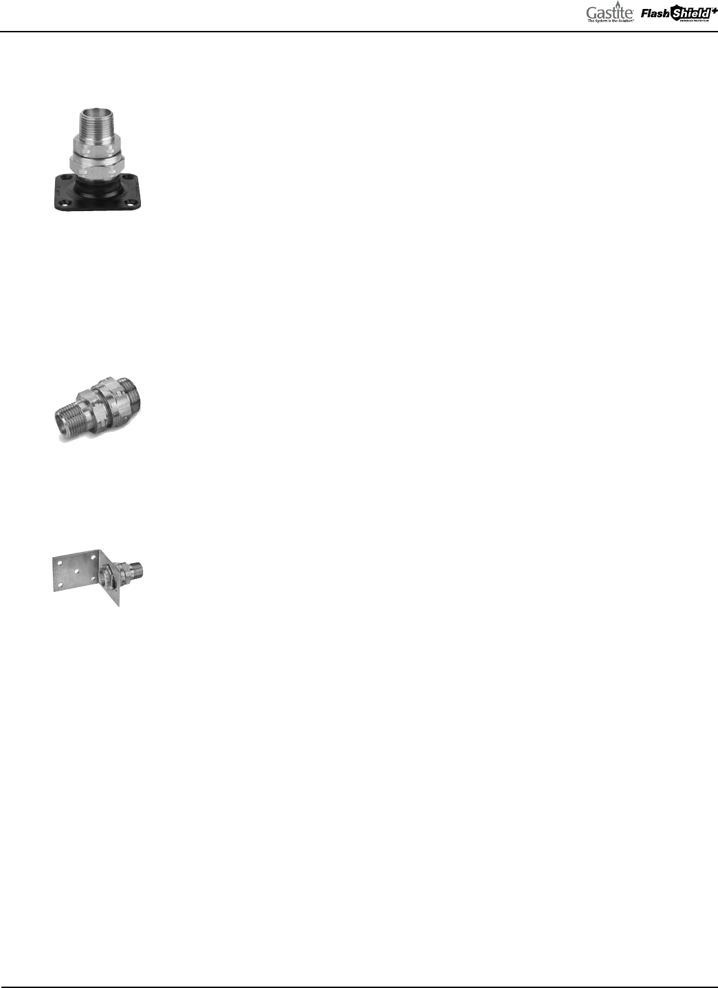
XR2/XR3 SERIES TERMINATION FITTING
(FLANGE/ADAPTER/NUT/BUSHING)
Termination Fitting
With Square Flange
Part No. Description Pkg. Qty.
XR2TRM-6-12 3/8" Term. Fitting-Square Flange – 1/2" NPT 12/Box
XR3TRM-8-12 1/2" Term. Fitting-Square Flange – 1/2" NPT 12/Box
XR3TRM-11-12 3/4" Term. Fitting-Square Flange – 3/4" NPT 12/Box
XR3TRM-16-6 1" Term. Fitting-Square Flange – 1" NPT 6/Box
XR3TRM-20-6 1-1/4" Term. Fitting-Square Flange – 1-1/4" NPT 6/Box
XR3TRM-24-4 1-1/2" Term. Fitting-Square Flange – 1-1/2" NPT 4/Box
XR3TRM-32-4 2" Term. Fitting-Square Flange - 2" NPT 4/Box
XR2TRM-6-12CB 3/8" Term. Fitting-Cast Bronze Flange – 1/2" NPT 12/Box
XR3TRM-8-CB-12 1/2" Term. Fitting-Cast Bronze Flange – 1/2" NPT 12/Box
XR3TRM-11-CB-12 3/4" Term. Fitting-Cast Bronze Flange – 3/4" NPT 12/Box
XR3TRM-16-CB-6 1" Term. Fitting-Cast Bronze Flange – 1" NPT 6/Box
XR3TRM-20-CB-6 1-1/4" Term. Fitting-Cast Bronze Flange – 1-1/4" NPT 6/Box
XR3TRM-24-CB-4 1-1/2" Term. Fitting-Cast Bronze Flange – 1-1/2" NPT 4/Box
XR2/XR3 SERIES TERMINATION FITTING WITH NO FLANGE (ADAPTER/NUT/BUSHING)
Termination Fitting
No Flange
Part No. Description Pkg. Qty.
XR2TRM-6-NF-12 3/8" Term. Fitting – 1/2" NPT with no Flange 12/Box
XR3TRM-8-NF-12 1/2" Term. Fitting – 1/2" NPT with no Flange 12/Box
XR3TRM-11-NF-12 3/4" Term. Fitting – 3/4" NPT with no Flange 12/Box
XR3TRM-16-NF-6 1" Term. Fitting – 1" NPT with no Flange 6/Box
XR3TRM-20-NF-6 1-1/4" Term. Fitting – 1-1/4" NPT with no Flange 6/Box
XR3TRM-24-NF-4 1-1/2" Term. Fitting – 1-1/2" NPT with no Flange 4/Box
XR3TRM-32-NF-4 2" Term. Fitting – 2" NPT with no Flange 4/Box
XR3 SERIES TERMINATION BRACKET FITTING (BRACKET/ADAPTER/NUT/BUSHING)
Term Bracket Fitting
Part No. Description Pkg. Qty.
XR3TRMBKT-8-12 1/2" Term. Bracket Fitting – 1/2" NPT 12/Box
XR3TRMBKT-11-12 3/4" Term. Bracket Fitting – 3/4" NPT 12/Box
XR3TRMBKT-16-6 1" Term. Bracket Fitting – 1" NPT 6/Box
XR3TRMBKT-20-6 1-1/4" Term Bracket Fitting – 1-1/4" NPT 6/Box
XR3TRMBKT-24-4 1-1/2" Term. Bracket Fitting – 1-1/2" NPT 4/Box
XR3TRMBKT-32-4 2" Term. Bracket Fitting – 2" NPT 4/Box
APPLICATION
• XR3 Fittings are used on both FlashShield+ black CSST and Gastite® yellow CSST.
• Straight Fittings connect the flexible gas tubing to gas supply, distribution manifolds or gas appliances.
• Tee Fittings create a branch line on tubing runs.
• Couplings allow for the splicing and additions to the flexible gas tubing.
MATERIAL / SPECIFICATIONS
• • Fitting adapter, bushings and nut—Brass.
• • Square Flange—Steel with zinc coating.
•
FEATURES AND BENEFITS
• Tool-less flare design; no special tools are required.
• Metal-to-metal seal, with no split rings, O-rings or gaskets.
• Self-guiding assembly to ensure a perfectly even flare.
• Exclusive, patented Jacket-Lock™ fitting eliminates exposed stainless steel beyond the nut.
• All components are fully reusable.
GASTITE DIVISION, TITEFLEX CORPORATION / 1116 Vaughn Parkway / Portland, TN 37148
800.662.0208 / www.gastite.com / [email protected]
12
SECTION 2: SYSTEM DESCRIPTIONS & COMPONENTS / JANUARY 2020
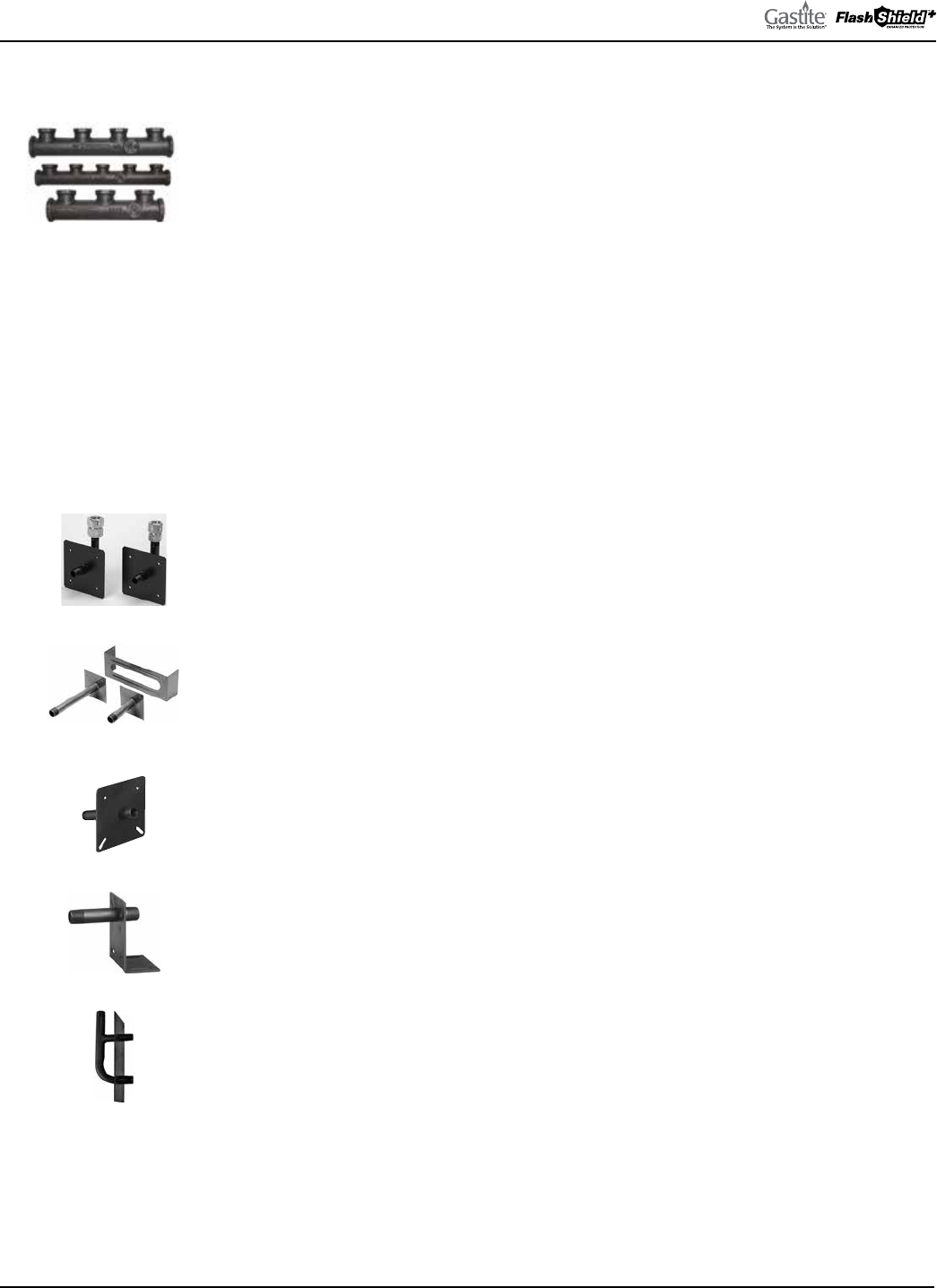
2.2.3 MANIFOLDS
MULTI-PORT MANIFOLDS
Cast Manifolds
Part No. Description Pkg. Qty.
3-PORTMAN Cast 3 port – 3/4"F x 3 @ 1/2"F x 1/2"F 1 Ea.
3-PORTMAN-1 Cast 3 port – 1/2" x 3 @ 1/2"F x 1/2"F 1 Ea.
4-PORTMAN-10 Cast 4 port – 3/4"F x 4 @ 1/2"F x 1/2"F 10/Box
5-PORTMAN Cast 5 port – 3/4"F x 1 @ 3/4"F x 4 @ 1/2"F x 1/2"F 1 Ea.
5-PORTMAN-1 Cast 5 port – 1"F x 1 @ 3/4"F x 4 @ 1/2"F x 3/4"F 1 Ea.
5-PORTMAN-2 Cast 5 port – 1-1/4"F x 5 @ 3/4"F x 1"F 1 Ea.
5-PORTMAN-3 Cast 5 port – 1-1/4"F x 5 @ 1/2"F x 1"F 1 Ea.
4-PORTMAN-2 Cast 4 port – 1-1/2"F x 4 @ 3/4"F x 1-1/2"F 1 Ea.
4-PORTMAN-3 Cast 4 port – 2"F x 4 @ 1"F x 1-1/2"F 1 Ea.
4-PORTMAN-M Cast 4 port – 3/4”F x 4 @ 1/2”F x 3/4”M 1 Ea.
APPLICATION
• Provides central distribution point for individual runs to each appliance.
MATERIAL/SPECIFICATIONS
• Cast 3, 4, and 5 Port – ASTM-A536-A Ductile Iron.
2.2.4 MODULAR STUB SYSTEM
MODULAR STUB SYSTEM
Angle Stub-Out
Deck Stub-Out
Double Stub-Out
Straight Stub-Outs
Optional Brackets
XR3-Appliance Stub-Outs
Part No. Description Pkg. Qty.
XR3-APSTUB-8-10 1/2"M x 1/2"M x 1-1/2" Stub length with 1/2" female fitting 10/Box
XR3-L-APSTUB-8-10 1/2"M x 1/2"M x 2-1/4" Stub length with 1/2" female fitting 10/Box
XR3-APSTUB-11-10 1/2"M x 1/2"M x 1-1/2" Stub length with 3/4" female fitting 10/Box
XR3-L-APSTUB-11-10 1/2"M x 1/2"M x 2-1/4" Stub length with 3/4" female fitting 10/Box
XR3-APSTUB-11-11-10 3/4"M x 3/4"M x 1-1/2" Stub length with 3/4" female fitting 10/Box
XR3-L-APSTB-11-11-10 3/4"M x 3/4"M x 2-1/4" Stub length with 3/4" female fitting 10/Box
1/2X6STUB-10 1/2"M x 6"L Straight Stub 10/Box
1/2X12STUB-10 1/2"M x 12"L Straight Stub 10/Box
3/4X6STUB-10 3/4"M x 6"L Straight Stub 10/Box
3/4X12STUB-10 3/4"M x 12"L Straight Stub 10/Box
1X6STUB-10 1"M x 6"L Straight Stub 10/Box
1X12STUB-10 1"M x 12"L Straight Stub 10/Box
1-1/4X6STUB-10 1-1/4"M x 6"L Straight Stub 10/Box
1-1/4X12STUB-10 1-1/4"M x 12"L Straight Stub 10/Box
1-1/2X6STUB-10 1-1/2"M x 6"L Straight Stub 10/Box
1-1/2X12STUB-10 1-1/2"M x 12"L Straight Stub 10/Box
ANGLE-STUB-01-10 1/2"M x 5-1/2"L x 72.5° Angle Stub 10/Box
STUB-BRACE Stub Bracket (optional) – Fits All 1 Ea.
DBLSTUB-1-10 3/4" Inlet x 1/2" & 3/4" Outlet 10/Box
DECKSTUB-1/2x3-10 1/2" x 3" Bracket Stub-Out 10/Box
APPLICATION
• All Stubs create a fixed point “stub-out” on a wall or floor surface for meter and appliance attachment.
• Angle Stub-Out mounting plate provided at a 72-1/2° angle to facilitate mounting to angled side of most fireplace
inserts.
MATERIAL / SPECIFICATIONS
• Schedule 40 steel pipe complying with material standard ASTM A-53.
• Exterior plating—Black oxide coating after all threading, forming and welding.
FEATURES AND BENEFITS
• Reduces the number of joints in the system where contractors typically fabricate “stub-outs” from rigid pipe nipples,
elbows and couplings.
• Provides a fixed-point termination for installations where the appliances are not yet installed.
• Creates a more polished look to the overall installation.
GASTITE DIVISION, TITEFLEX CORPORATION / 1116 Vaughn Parkway / Portland, TN 37148
800.662.0208 / www.gastite.com / [email protected]
13
SECTION 2: SYSTEM DESCRIPTIONS & COMPONENTS / JANUARY 2020
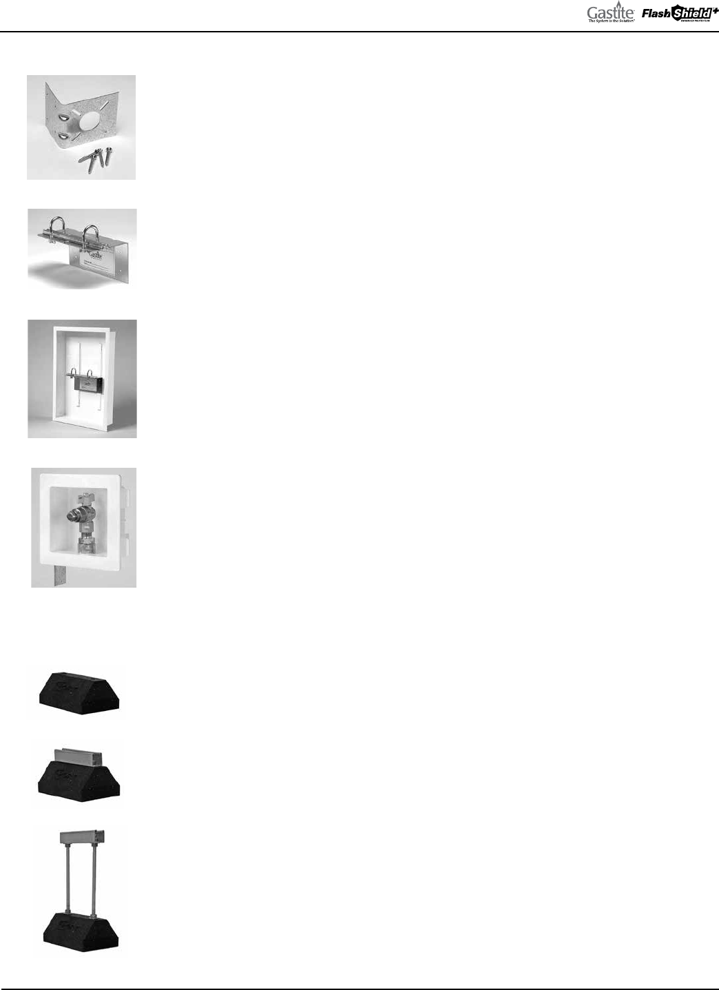
2.2.5 MOUNTING HARDWARE
MOUNTING HARDWARE
Manifold Bracket
Gas Load Center
XR3-Outlet Box
Termination Bracket
Part No. Description Pkg. Qty.
LBRACE-1-20 Term. Fitting Mounting Kit – Fits 3/8" - 1" CSST 20/Box
MBRACE-1-10 Manifold Mounting Kit – See below for mounting options 10/Box
MBRACE-3-10 Manifold Mounting Kit – See below for mounting options 10/Box
GLC1 Gas Load Center Kit – 14-1/2" x 24" x 3-1/2" 1 Ea.
MSTRAPS-6-250 Metal Tubing Strap – Fits 3/8" CSST 250/Box
MSTRAPS-8-250 Metal Tubing Strap – Fits 1/2" CSST 250/Box
MSTRAPS-11-150 Metal Tubing Strap – Fits 3/4" CSST 150/Box
MSTRAPS-16-100 Metal Tubing Strap – Fits 1" CSST 100/Box
MSTRAPS-20-50 Metal Tubing Strap – Fits 1-1/4" CSST 50/Box
MSTRAPS-24-50 Metal Tubing Strap – Fits 1-1/2" CSST 50/Box
MSTRAPS-32-25 Metal Tubing Strap – Fits 2" CSST 25/Box
XR3OUTLETBOX-8 Recessed gas outlet box kit with 1/2" XR3 Fitting 1 Kit
XR3OUTLETBOX-11 Recessed gas outlet box kit with 3/4" XR3 Fitting 1 Kit
XR3OUTLETBOX-FR8 Firestop gas outlet box kit with 1/2" XR3 Fitting 1 Kit
XR3OUTLETBOX-FR11 Firestop gas outlet box kit with 3/4" XR3 Fitting 1 Kit
APPLICATION
• Termination Bracket provides mounting surface for termination fitting assembly.
• Manifold Bracket provides mounting platform for manifolds, supplied with adhesive port labeling.
• Gas Load Center creates a recessed cabinet for a more polished look to manifold assembly.
• XR3OUTLETBOX creates a secure recessed termination point for connection to moveable appliances.
MATERIAL / SPECIFICATIONS
• Termination Fitting—16 gauge galvanized sheet metal.
• MBRACE-1 Mounting Kit made of 16 gauge galvanized sheet metal.
- Fits 3-PORTMAN, 4-PORTMAN, 5-PORTMAN and 4-PORTMAN-M.
• MBRACE-3 Mounting Kit made of 14 gauge galvanized sheet metal.
- Fits 5-PORTMAN-1, 5-PORTMAN-2, 5-PORTMAN-3 and 4-PORTMAN-2.
• 4-PORTMAN-3 requires installer supplied mounting brackets.
• Gas Load Center—20 gauge steel with a white, polyester powder coat finish.
• Metal Tubing Straps—22, 20 or 18 gauge sheet metal, depending on size.
2.2.6 PIPE SUPPORT SYSTEM
PIPE SUPPORT SYSTEM
RB2
RB0
RB1
Part No. Description Pkg. Qty.
RB0-10-4 Rubber Support Block (10"L x 4"H) 1 Ea.
RB1-10-5 Rubber Support Block w/ 7/8" Galv Steel Channel (10"L x 5"H) 1 Ea.
RB1-29-5 Rubber Support Block w/ 7/8" Galv Steel Channel (29"L x 5"H) 1 Ea.
RB2-10-12 Rubber Support Block w/Adj height 7/8" Galv Steel Channel (10"L x 5"–12"H) 1 Ea.
APPLICATION
• Effectively anchors and supports lightweight Gastite CSST, as well as other fuel gas piping materials to any roofing
membrane.
MATERIAL / SPECIFICATIONS
• Made of 100% recycled material, UV resistant and waterproof.
• Will not damage expensive roof membranes.
• Installs on any roof with or without standard roof adhesives.
GASTITE DIVISION, TITEFLEX CORPORATION / 1116 Vaughn Parkway / Portland, TN 37148
800.662.0208 / www.gastite.com / [email protected]
14
SECTION 2: SYSTEM DESCRIPTIONS & COMPONENTS / JANUARY 2020
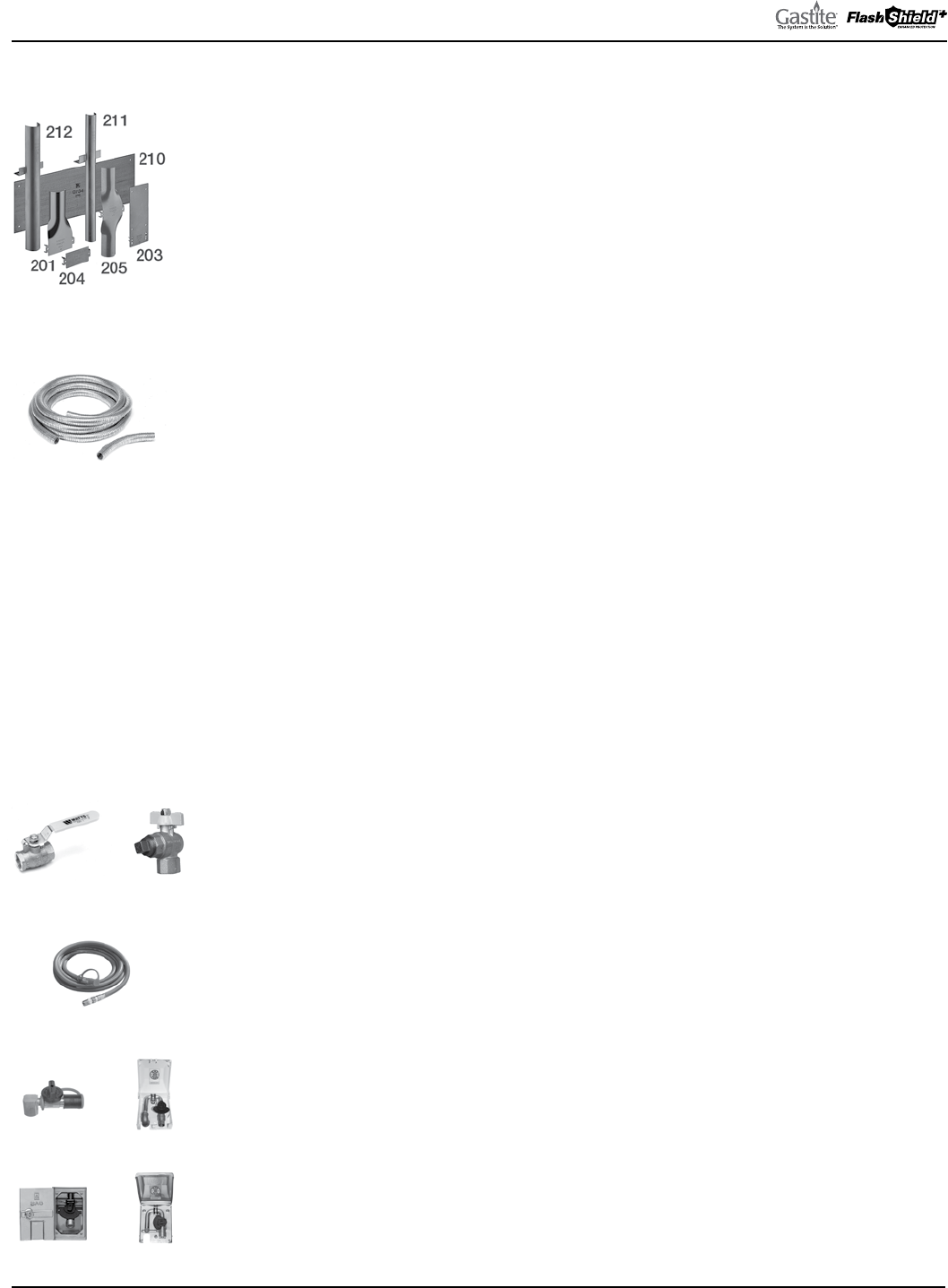
2.2.7 STRIKE PROTECTION
PROTECTION DEVICES – STRIKER PLATES & SILICONE TAPE
Part No. Description Pkg. Qty.
TFM204-100 Quarter Striker Plate – 3" x 2" 100/Box
TFM201-50 Half Striker Plate – 3" x 7" 50/Box
TFM203-50 ree-Quarter Striker Plate – 3" x 8" 50/Box
TFM205-25 Full Striker Plate – 3" x 12" 25/Box
TFM210-10 6" x 17" Striker Plate 10/Box
TFM211-25 Full (Drop-In) Striker Plate – 1/2" & 3/4" CSST 25/Box
TFM212-25 Full (Drop-In) Striker Plate – 1" & 1 1/4" CSST 25/Box
SIL-TAPE Self Bonding Yellow Silicone Tape – 1" x .015" x 12 yd / roll 1 Ea.
SIL-TAPE-B Self Bonding Black Silicone Tape – 1" x .015" x 12 yd / roll 1 Ea.
Part No. Description Pkg. Qty.
FLOPPY16 1" Coil steel conduit – Fits 1/2" CSST 50 Ft/Coil
FLOPPY20 1-1/4" Coil steel conduit – Fits 3/4" CSST 25 Ft/Coil
FLOPPY24 1-1/2" Coil steel conduit – Fits 1" CSST 25 Ft/Coil
FLOPPY28 1-3/4" Coil steel conduit – Fits 1-1/4" CSST 25 Ft/Coil
FLOPPY36 2-1/4" Coil steel conduit – Fits 1-1/2" CSST 25 Ft/Coil
FLOPPY48 3" Coil steel conduit – Fits 2" CSST 25 Ft/Coil
Part No. Description Pkg. Qty.
LFLOPPY-16-50 1" – Cut to 1 foot length – Fits 1/2" CSST 50/Box
LFLOPPY-20-25 1-1/4" – Cut to 1 foot length – Fits 3/4" CSST 25/Box
LFLOPPY-24-25 1-1/2" – Cut to 1 foot length – Fits 1" CSST 25/Box
LFLOPPY-28-25 1-3/4" – Cut to 1 foot length – Fits 1-1/4" CSST 25/Box
LFLOPPY 36-25 2-1/4" – Cut to 1 foot length – Fits 1-1/2" CSST 25/Box
LFLOPPY-48-25 3" – Cut to 1 foot length – Fits 2" CSST 25/Box
APPLICATION
• Striker plates used for protection where flexible gas piping passes through structural members and is
restricted from moving to avoid nails, screws and other potential puncture threats.
• Steel conduit is used to provide additional protection where striker plates cannot be easily installed.
MATERIAL / SPECIFICATIONS
• Striker Plates – 16 gauge AISI1050 Carbon Steel Hardened to Rc 45.
• Steel Conduit – Strip wound interlocking steel.
2.2.8 SHUT-OFF VALVES AND QUICK CONNECTS
SHUT-OFF VALVES
Part No. Description Pkg. Qty.
T100-1/2-20 1/2" Ball Valve rated to 125 PSI 20/Box
T100-3/4-10 3/4" Ball Valve rated to 125 PSI 10/Box
T100-1-1/4-5 1-1/4" Ball Valve rated to 125 PSI 5/Box
T90-1/2-10 1/2" 90 Degree Shut-Off Valve 10/Box
T90-3/4-10 3/4" 90 Degree Shut-Off Valve 10/Box
OUTDOOR FLEX CONNECTOR WITH QUICK CONNECT PLUG
Part No. Description Pkg. Qty.
OUTFLEX-3/8 3/8" Outdoor Flex Connector, 10-ft, 3/8" Male plug X 3/8" Female Flare
Swivel, 3/8" MPT adapter (43 CFH)*
1 Ea.
OUTFLEX-1/2 1/2" Outdoor Flex Connector, 10-ft, 1/2" Male plug X 1/2" Female Flare
Swivel, 1/2" MPT adapter (87 CFH)*
1 Ea.
*Capacity of flex connector and QC vlave combination, @ 1" w.c. pressure drop
QUICK CONNECT VALVES
Part No. Description Pkg. Qty.
T103029 3/8" Quick Connect Valve, 90 deg, 1/2" FPT inlet 1 Ea
T104123 1/2" Quick Connect Valve, Straight, 1/2" FPT inlet 1 Ea
QCBOXPW 3/8" QC Valve Box (white PVC) 1/2" FPT inlet, Surface Mount, Lockable
1 Ea
QCBOXPG 3/8" QC Valve Box (grey PVC) 1/2" FPT inlet, Surface Mount, Lockable
1 Ea
QCBOXSS 3/8" QC Valve Box (S.S.) 1/2" FPT inlet, Recessed, Lockable Door
1 Ea
BBQ-SS-50 1/2" QC Valve Box (S.S.) 1/2" FPT inlet, Surface Mount, Lockable Door
1 Ea
Striker Plates
Steel Conduit Coil &
Cut Length
Outdoor Flex Connector
Ball Valve 90˚ Ball Valve
QC Valve QC Valve Box (PVC)
QC Valve Box (SS)
Recessed
QC Valve Box (SS)

GASTITE DIVISION, TITEFLEX CORPORATION / 1116 Vaughn Parkway / Portland, TN 37148
800.662.0208 / www.gastite.com / [email protected]
15
SECTION 2: SYSTEM DESCRIPTIONS & COMPONENTS / JANUARY 2020
2.2.9 GASTITE
®
ACCESSORIES
TUBING CUTTERS AND ACCESSORIES
Part No. Description Pkg. Qty.
GTCUTTER-SM Yellow cutter with flat rollers – 3/8"–1" Gastite and FlashShield+ 1 Ea.
GTCUTTER-LG Yellow cutter with flat rollers – Up to 2" Gastite and 1-1/2" FlashShield+ 1 Ea.
GTBLADE-SM-5 Replacement blade for GTCUTTER-SM and GTCUTTER-SM2 (19mm) 5 Ea.
GTBLADE-LG2-5 Replacement blade for GTCUTTER-LG2 and GTCUTTER-LG (30mm) 5 Ea.
APPLICATION
• Tubing Cutters, fitted with cutting wheel designed to cut stainless steel, create clean cuts for optimal flaring of tubing.
MATERIAL / SPECIFICATIONS
• Aluminum alloy body.
JACKET STRIPPING TOOL
Jacket Stripping Tool
Part No. Description Pkg. Qty.
STRP4-8-11-24 1/2" + 3/4" Jacket Stripping Tool 24/Pkg.
STRP4-16-20-24 1" + 1-1/4" Jacket Stripping Tool 24/Pkg.
2.2.10 BONDING CLAMPS
BONDING CLAMPS
Bonding Clamps
Part No. Description Pkg. Qty.
CWP1JSH Bonding Clamp for 3/8" and 1/2" Fittings 1 Ea.
CWP2JSH Bonding Clamp for 3/4", 1" and 1-1/4" Fittings 1 Ea.
CWP3JSH Bonding Clamp for 1-1/2" and 2" Fittings 1 Ea.
2.2.11 SYSTEM IDENTIFICATION
SYSTEM IDENTIFICATION
Adhesive Label
Metal Tag
Part No. Description Pkg. Qty.
EPAL-1-100 Adhesive Labels for elevated pressure identification 100/Roll
EPMT-1-100 Metal Tags for Uniform Plumbing Code compliance 100/Pkg.
Tubing Cutters
GASTITE DIVISION, TITEFLEX CORPORATION / 1116 Vaughn Parkway / Portland, TN 37148
800.662.0208 / www.gastite.com / [email protected]
16
SECTION 2: SYSTEM DESCRIPTIONS & COMPONENTS / JANUARY 2020
Pietro Fiorentini
Regulators
Pietro Fiorentini
Regulators
OARA Regulators
OARA Regulators
Maxitrol Regulators
Maxitrol Regulators
Maxitrol Regulators
with OPD
LINE REGULATORS - NATURAL GAS, 8" W.C. OUTLET SETPOINT
MAXITROL REGULATORS
Part No. Regular Application NPT Capacity*(CFH) Pkg. Qty Wt. (Lbs.)
T325-3-44
2 PSI 1/2" 258 1 0.8
T325-5-2
2 PSI 1/2" 516 1 1.8
T325-5-44
2 PSI 3/4" 620 1 1.8
T325-5-3
2 PSI 1" 620 1 1.8
T325-7AL-NG01
2 PSI 1-1/4" 1,291 1 3.5
MAXITROL O.P.D.'S
Part No. Regular Application NPT Capacity*(CFH) Pkg. Qty Wt. (Lbs.)
T325-3L48 5 PSI 1/2" 207 1 1.5
T325-5AL600 5 PSI 3/4" 439 1 3.4
T325-7L-210D** 5 PSI 1-1/4" 1,291 1 9.2
OARA REGULATORS
Part No. Regular Application NPT Capacity*(CFH) Pkg. Qty Wt. (Lbs.)
REG-8-300 2 PSI 1/2" 238 1 0.8
REG-8-600 2 PSI 3/4" 462 1 1.9
PIETRO FIORENTINI REGULATORS
Part No. Regular Application NPT Capacity*(CFH) Pkg. Qty Wt. (Lbs.)
30051-NG 2 PSI 1/2" 552 1 1.7
30052-NG 2 PSI 3/4" 665 1 1.7
30053-NG 2 PSI 1" 893 1 1.6
30153-NG 2 PSI 1-1/4" 3,735 1 7.4
LINE REGULATORS - PROPANE, 11" W.C. OUTLET SETPOINT
MAXITROL REGULATORS
Part No. Regular Application NPT
Capacity*
(000 BTU/H)
Pkg. Qty
Wt.
(Lbs.)
T325-3-44P
2 PSI 1/2" 368 1 0.8
T325-5-44P
2 PSI 3/4" 916 1 1.8
T325-5-3P
2 PSI 1" 916 1 1.8
OARA REGULATORS
Part No. Regular Application NPT
Capacity*
(000 BTU/H)
Pkg. Qty
Wt.
(Lbs.)
REG-11-300 2 PSI 1/2" 344 1 0.8
REG-11-600 2 PSI 3/4" 669 1 1.9
PIETRO FIORENTINI REGULATORS
Part No. Regular Application NPT
Capacity*
(000 BTU/H)
Pkg. Qty
Wt.
(Lbs.)
30052-LP 2 PSI 3/4" 965 1 1.7
2.2.12 LINE REGULATORS
*Natural gas, 0.60 specific gravity. 1 PSI inlet, 8" w.c. outlet
See FlashShield+ Design & Installation guide, table 4-7 for further sizing info.
**Vent limiter not available for -7 OPD
*Propane, 1.52 specific gravity. 1 PSI inlet, 11" w.c. outlet
See FlashShield+ Design & Installation guide, table 4-8 for further sizing info.
VENT PROTECTORS
Part No. Description
Pkg.
Qty
Wt.
(Lbs.)
VP3 Maxitrol, Outdoor Vent Protector, fits 1/8" NPT vent orifice (fits -3 and 300 series) 1 Ea. 0.1
VP5 Maxitrol, Outdoor Vent Protector, fits 3/8" NPT vent orifice (fits -5 and 600 series) 1 Ea. 0.1
VP14 Pietro Fiorintini, Outdoor Vent Protector, fits 1/4" NPT vent orifice (fits 30051, 52, 53) 1 Ea. 0.1
VP12 Pietro Fiorintini, Outdoor Vent Protector, fits 1/2" NPT vent orifice (fits 30153 and -7) 1 Ea. 0.1
APPLICATION
Vent protector is used (as one option) when vent-limiter is removed for outdoor regulator installation
Vent Protectors

GASTITE DIVISION, TITEFLEX CORPORATION / 1116 Vaughn Parkway / Portland, TN 37148
800.662.0208 / www.gastite.com / [email protected]
17
GASTITE/FLASHSHIELD
+
CSST WORKSHEET
PROJECT / LOCATION: DRAWN BY:
CONTACT PHONE: DATE:
DESCRIPTION
SYSTEM DESCRIPTION
SYSTEM DATA AND REQUIREMENTS
NAME OF
RUN
SUPPLY
PRESSURE
(LBS. OR IN.)
LENGTH OF
RUN (FT.)
LOAD OF RUN
(CFH)
PRESS. DROP
(LBS. OR IN.)
TUBE DIAMETER
(SIZE OR IN.)
DELIVERY
PRESS.
(LBS. OR IN.)
COMMENTS
A
B
C
D
E
F
G
H
I
J
K
L
M
N
O
To be copied: For Planning and Design of the Gastite®/FlashShield+ Piping System. Visit www.gastite.com for a downloadable version of this worksheet.
GASTITE DIVISION, TITEFLEX CORPORATION / 1116 Vaughn Parkway / Portland, TN 37148
800.662.0208 / www.gastite.com / [email protected]
18
SECTION 3: SYSTEM CONFIGURATION / JANUARY 2020
SECTION 3.0 SYSTEM CONFIGURATION
3.1 CONFIGURATION
3.1.1 INTRODUCTION
is section is intended to help in the design and sizing of both Gastite and FlashShield
+
CSST fuel gas piping systems.
e form -printed on the previous page is to aid in keeping track of the system requirements as well as organizing the
system configuration and sizing numbers. Refer to the Gastite web site (www.gastite.com) for additional sizing tools.
e Gastite/FlashShield
+
gas piping system is required to be tested, listed, and installed in accordance with the Standard
For Fuel Gas Piping Systems Using Corrugated Stainless Steel Tubing, ANSI LC1. is standard, among other things,
requires the manufacturer to provide installation instructions including the necessary pipe sizing tables and methods of
sizing.
3.1.2 SYSTEM REQUIREMENTS
• Determine the local piping restrictions prior to installing the flexible gas piping. Confirm that the local administrative
authority has accepted the use of flexible gas piping. Corrugated Stainless Steel Tubing has been accepted by all major code
bodies, but local or state adoption of these codes often lags behind. Check with the local administrative authority or an
authorized
Gastite/FlashShield
+
distributor for approval in your area.
• Determine metered (supply) pressure. A gauge can be used to measure the supply pressure or the utility will provide a supply
pressure rating.
• Determine appliance demand. Every appliance will have a manufacture’s nameplate containing BTUH or CFH requirements
as well as minimum and maximum operating pressures.
• Refer to building plans or prepare a sketch showing the location of each appliance. When preparing this sketch keep in mind
the safest, easiest, and shortest distance locations to run the piping. Label the pipe segments and the corresponding lengths.
Take note of fittings needed e.g. tees, manifolds, reducers.
3.1.3 REFERENCE DATA FOR PROPER SYSTEM SIZING
• Determine the total capacity needed for all appliances. CFH or BTUH equivalents for natural gas or propane can be
obtained from the local gas utility or propane supplier. e capacity tables within this guide or other approved CSST tables
should be used to determine pipe sizing for both Gastite and
FlashShield
+
needed to meet BTUH input load requirements.
TABLE 3-1 REFERENCE DATA FOR PROPER SYSTEM SIZING
PRESSURE CONVERSION FACTORS FUEL GAS INFORMATION
1/4 PSI = 6.921"WC = (approx. 7"WC) Natural Gas Propane
1/2 PSI = 13.842"WC = (approx. 14"WC) BTU per Cubic Foot = 1000 2516
1 PSI = 27.6 8 4" WC = (approx. 28"WC) Specific Gravity = 0.6 1.52
2 PSI = 55.368"WC = (approx. 56"WC)
Note: “Pressure Drop Curves for Gastite® CSST” are expressed in terms of Cubic
Feet per Hour (CFH). To determine the CFH for Natural Gas, divide the BTU
load by 1000. To determine the CFH for Propane, divide the BTU load by 2516.
5 PSI = 138.42"WC = (approx. 140"WC)
Refer to Section 7.0 for gases with a specific gravity other than 0.60.
GASTITE DIVISION, TITEFLEX CORPORATION / 1116 Vaughn Parkway / Portland, TN 37148
800.662.0208 / www.gastite.com / [email protected]
19
SECTION 3: SYSTEM CONFIGURATION / JANUARY 2020
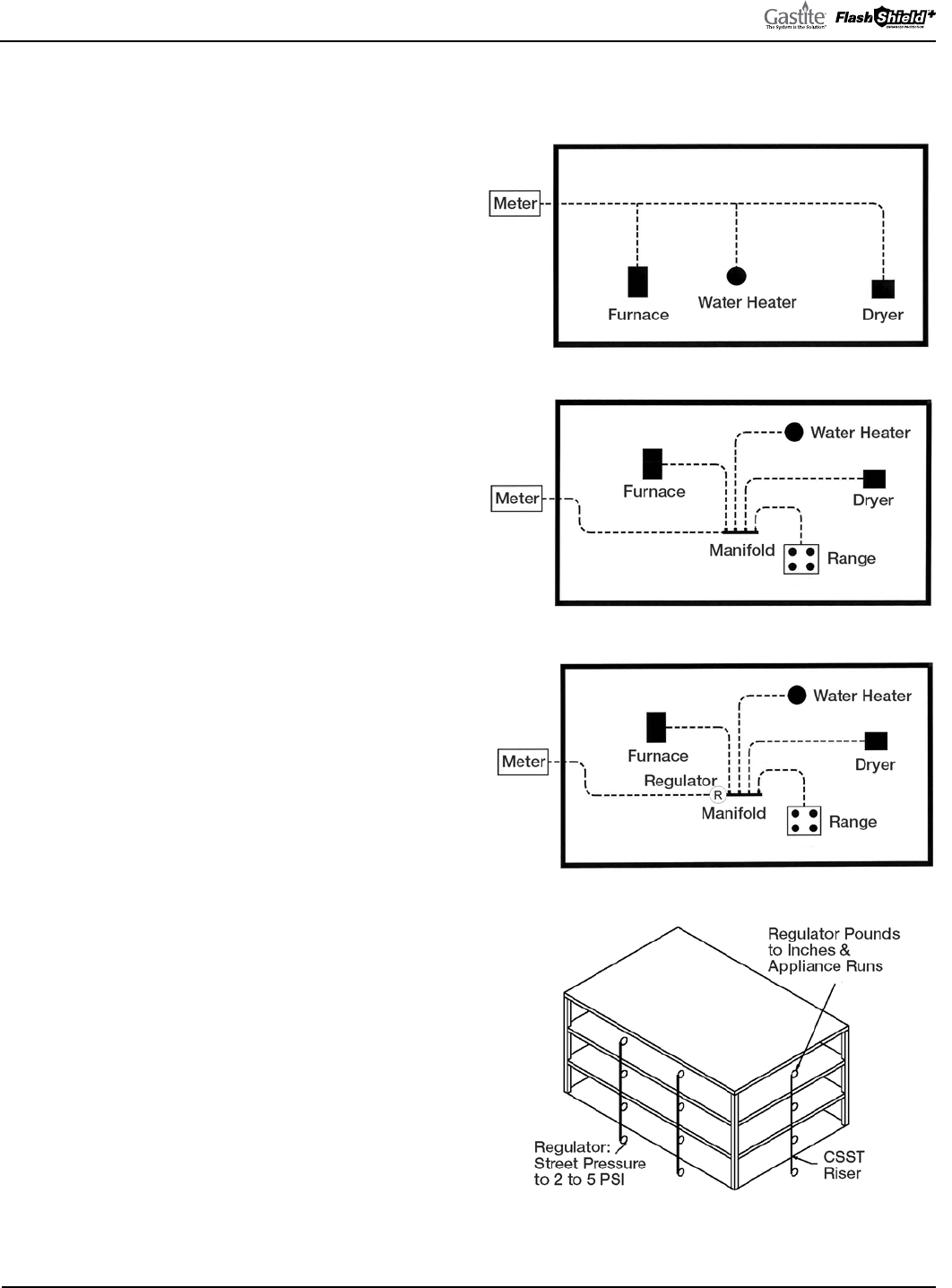
3.1.4 DETERMINING SYSTEM LAYOUT
A) SERIES SYSTEMS
A series layout (Fig 3-1) is the most common arrangement
utilized for rigid pipe systems for low pressure. ese usually
consist of a main run (header) with tees branching off to each
appliance. In a traditional series system, the service pressure
down stream of the meter is typically less than 1/2 PSI.
B) PARALLEL SYSTEMS
In a parallel system (Fig. 3-2) a main run from the meter
supplies a central distribution manifold. e appliances are
serviced by individual runs from the manifold. e manifold
station is best located close to the greatest load, typically the
boiler or furnace.
C) DUAL PRESSURE SYSTEM
A dual pressure system (Fig. 3-3, 3-4) incorporates two
operating pressures downstream from the meter. e first
pressure, set by the service regulator at the meter, is usually
2 PSI but can be higher or lower depending on code
restrictions and gas company policy. is part of the system
is sized separately and ends at the pounds-to-inches regulator
inlet. Tables 4-7, 4-8 and 4-9 show maximum loads vs. inlet
pressures to the regulator.
e second pressure, at the outlet of the pounds-to-inches
regulator, is under 1/2 PSI; usually 8"WC for natural gas
and 11"WC for propane regulators supplied by Gastite.
Generally, a parallel system requires a higher total footage
of smaller diameter tubing and fewer fittings compared to a
series layout.
Fig. 3-1
Fig. 3-2
Fig. 3-3
Fig. 3-4
Multi-Unit Apartment Building

GASTITE DIVISION, TITEFLEX CORPORATION / 1116 Vaughn Parkway / Portland, TN 37148
800.662.0208 / www.gastite.com / [email protected]
20
SECTION 3: SYSTEM CONFIGURATION / JANUARY 2020
D) MULTIPLE MANIFOLD SYSTEMS
For those installations in which the energy load demand is large or the appliances are installed throughout the structure
with long distances from the meter, a multiple manifold system may be used (Fig. 3-5, 3-6). Elevated pressure systems are a
safe, efficient method of providing for larger BTUH load demands while maintaining smaller pipe diameters.
E) COMBINATION STEEL / CSST SYSTEM (HYBRID)
In a hybrid system (Fig. 3-7), corrugated stainless steel
tubing is used in combination with rigid pipe or copper
tubing. In lower pressure systems it is often advantageous
to use both CSST and rigid pipe to help minimize pressure
drops typically encountered on systems with high loads and/
or long runs. Gastite flexible gas piping is approved for use in
combination with all approved fuel gas-piping materials by
using approved pipe threads at the interface.
F) ELEVATED PRESSURE SYSTEM
In a complete elevated pressure system (Fig. 3-8), corrugated
stainless steel tubing is used to deliver pressures in excess of
1/2 PSI to a pounds-to-inches regulator positioned directly
in front of each appliance. is is an alternate method of
installation used to minimize pipe size on systems with high
loads and/or long runs. Regulators shall be sized per the
largest single appliance, see Table 4-10.
Fig. 3-5 Fig. 3-6
Fig. 3-7
Fig. 3-8

GASTITE DIVISION, TITEFLEX CORPORATION / 1116 Vaughn Parkway / Portland, TN 37148
800.662.0208 / www.gastite.com / [email protected]
21
SECTION 3: SYSTEM CONFIGURATION / JANUARY 2020
3.1.5 ALLOWABLE PRESSURE DROP
With respect to gas pipe sizing, the intent of all model codes is to ensure that there is sufficient gas volume and pressure
supplied to the appliance for proper operation. Language from the International Fuel Gas Code clearly illustrates this point.
“Allowable Pressure Drop: e design pressure loss on any piping system under maximum probable
flow conditions, from point of delivery to the inlet connection of the equipment, shall be such that
the supply pressure at the equipment is greater than the minimum pressure required for proper
equipment operation.”
e Gastite/FlashShield
+
low-pressure tables are intended for use at a system pressure of 1/2 PSI or less, which
encompasses the range of commonly delivered utility pressures and equipment requirements. To determine which table
to use determine the system’s allowable pressure drop. e appropriate pressure drop can be calculated by subtracting the
appliance inlet pressure (typically 5"WC for NG, 10.5"WC for LPG) from the gas source pressure (gas meter for NG,
secondary regulator for LPG). Use the Gastite/FlashShield
+
capacity table labeled with the appropriate allowable pressure
drop and gas type. Increasing the available pressure drop will increase the available BTUHs, thus decreasing pipe sizes. It is
advantageous to allow for a larger pressure drop.
e Summation Method of pipe sizing calculates the actual pressure loss through each section of pipe. e sum of all the
losses is subtracted from the starting supply pressure to determine the inlet pressure to each appliance. e appliance inlet
pressure must fall within the manufacturer’s range for proper operation.
Note: Regardless of sizing method employed, the typical NG system should be sized for a minimum appliance inlet
pressure of 5"WC and 10.5"WC for LPG system. Pressures less than the typical minimums may be sufficient for proper
appliance operation but should be reviewed with the manufacturers’ input rating and the local administering authority.
Conversely, some modern higher performance appliances require an inlet pressure greater than the typical minimums.
Check the manufacturers’ input rating before sizing.
3.1.6 SIZING METHODS
Capacity Tables from this Guide (Section 7) or appropriate code approved tables must be used when sizing Gastite/
FlashShield
+
CSST. e sizing tables used in this manual include losses for four 90-degree bends, and two end fittings.
Tubing runs with larger numbers of bends and/or fittings should be increased by an equivalent length of tubing to the
following equation: L = 1.3 (N): where “L” is additional length of tubing, and “N” is the number of additional fittings, or
90 degree bends.
Gastite’s Longest Run tables and Summation tables are produced from the same fluid flow equations. As such, they will
provide the same results taking into account any rounding of distance or capacity. ese fluid equations come from data
produced by a third party laboratory. e testing was performed on actual Gastite/FlashShield
+
CSST while tables in the
code reflect the most restrictive CSST.
THE LONGEST RUN METHOD:
A modified version of the longest run (commonly used in conventional rigid pipe systems) is presented here and used in
Examples 1, 2 & 3. is method may be used for any pressure as listed in the appropriate Capacity Table.
For sizing each length of pipe, determine the total gas load for all appliances serviced by that section and the maximum
distance over which that particular section delivers gas. e maximum distance includes overall length from the meter to
the furthest appliance serviced by that run. Refer to Section 7 Capacity Tables for the maximum flow capacity of CSST at
the required piping length.

GASTITE DIVISION, TITEFLEX CORPORATION / 1116 Vaughn Parkway / Portland, TN 37148
800.662.0208 / www.gastite.com / [email protected]
22
SECTION 3: SYSTEM CONFIGURATION / JANUARY 2020
For sizing dual-pressure systems, the piping from the meter to the pounds-to-inches regulator is sized separately from the
piping downstream of the regulator outlet. is procedure is shown in Examples 4 & 5.
Sizing for a Hybrid System (one that includes both rigid pipe and CSST) is accomplished by using the longest run
method to determine the appropriate pipe size for a given load and run length. Each segment of the piping system uses the
appropriate sizing table for that particular piping material. is procedure is shown in Examples 6 & 7.
SUMMATION METHOD:
An alternative sizing method is the Summation Method which considers a summation of the pressure losses through
each section of piping. is procedure is utilized for the designer whose requirements are not satisfied by the previously
described methods. e summation method can be used for system pressures and pressure drops other than indicated in
the sizing tables for longest run. is method allows full use of the maximum flow capacity of CSST. In this fashion, a
designer can minimize piping size (or maximize flow capacity) with greater accuracy in more complicated arrangements.
e summation method is shown in Examples 8 & 9.
3.1.7 MODIFYING AN EXISTING SYSTEM
Gastite/FlashShield
+
fittings transition from CSST to pipe thread (NPT) and may be run in conjunction with all other
approved fuel gas piping (iron pipe, polyethylene tubing, copper tubing, etc.). When adding appliances to an existing
system the installer must verify whether the existing system, upstream of the lines to be added, can support the additional
load.
A retrofitted line, even when properly sized, added to a system that can’t support the additional load, can adversely effect
all the other appliances in the system.
When the existing system will not support the additional load several installation options exist. A new trunk line(s) can be
run replacing the under-sized system upstream of the retrofitted appliances. A dedicated trunk line can be run from the gas
source to the new appliance. e system pressure may be elevated, thus increasing the allowable pressure drop, after which
the existing trunk lines may afford sufficiently higher flow capacity to handle the existing and new appliances.
If the piping is visible or the existing run lengths are known, the entire system can be resized using either aforementioned
sizing method (Longest Run or Summation). e system shall be resized with an appropriate sizing table based on the
affordable pressure drop. When the piping is not visible or accessible for measurement, approximated lengths should be
rounded up.
3.2 SIZING PROCEDURES AND EXERCISES
3.2.1 SIZING EXAMPLES
While the following examples show typical applications of the sizing methods they do not address all of the system
configurations in which they can be used. In general, Longest Run and Summation can be used with any pressure or
system configuration (series, parallel, dual-pressure, hybrid, etc.).
e following exercises illustrate various design layouts, pressure drops and sizing methods. To further highlight the
differences in methods and designs, examples 1-8 use the same appliance layout and load.
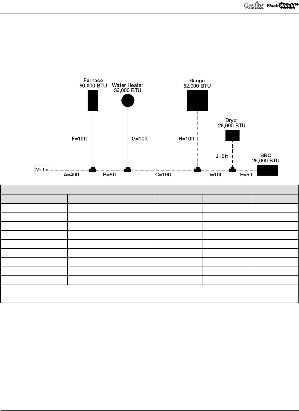
GASTITE DIVISION, TITEFLEX CORPORATION / 1116 Vaughn Parkway / Portland, TN 37148
800.662.0208 / www.gastite.com / [email protected]
23
SECTION 3: SYSTEM CONFIGURATION / JANUARY 2020
3.2.2 EXAMPLE 1: SERIES SYSTEM – 6"WC
Figure 3-9 below shows a typical single-family house installation with five (5) appliances. e piping is arranged in series
with a main run branching at the appliances. e utility company’s supply pressure (downstream of the meter) is 6"WC.
e utility company advises that the specific gravity of the gas delivered will be 0.60 and the energy content is 1 CFH =
1000 BTUH. e allowable pressure drop across the system has been determined to be 1.0"WC (supply pressure 6"WC –
appliance requirement 5"WC).
Fig. 3-9
TABLE 3-2
SECTION DESCRIPTION LOAD DELIVERED BY SECTION SECTION LENGTH RUN LENGTH TUBE SIZE
“A” – Trunk 221 CFH = 221,000 BTUH 40 feet 70 feet 1" CSST
“B” – Trunk 141 CFH = 141,000 BTUH 5 feet 70 feet 1" CSST
“C” – Trunk 105 CFH = 105,000 BTUH 10 feet 70 feet 1" CSST
“D” – Trunk 53 CFH = 53,000 BTUH 10 feet 70 feet 3/4" CSST
“E” – BBQ 25 CFH = 25,000 BTUH 5 feet 70 feet 1/2" CSST
“F” – Furnace 80 CFH = 80,000 BTUH 10 feet 50 feet 3/4" CSST
“G” – Water Heater 36 CFH = 36,000 BTUH 10 feet 55 feet 1/2" CSST
“H” – Range 52 CFH = 52,000 BTUH 10 feet 65 feet 3/4" CSST
“J” – Dryer 28 CFH = 28,000 BTUH 5 feet 70 feet 1/2" CSST
Run Length for Trunk Sections = Distance from meter to furthest appliance (Longest Run)
Run Length for Appliance Sections = Distance from meter to each appliance
SIZING RUN “A”
• Run “A” is sized by the total load of all appliances and the run length from the meter to the furthest appliance
• e total load of all appliances is 80 + 36 + 52 + 28 + 25 = 221CFH
• e run length to the BBQ (furthest appliance) is 40 + 5 + 10 + 10 + 5 = 70ft
• Referring to Table 7-2 (1.0"WC pressure drop): for a 70ft run, 1" CSST has a capacity over 221CFH (actual: 227)
SIZING RUN “B”
• Run “B” is sized by the total load of all supplied appliances and the run length from the meter to the furthest appliance
• e total load of the supplied appliances is 36 + 52 + 28 + 25 = 141CFH
• e run length to the BBQ (furthest appliance) is 40 + 5 + 10 + 10 + 5 = 70ft
• Referring to Table 7-2 (1.0"WC pressure drop) for a 70ft run, 1" CSST has a capacity over 141CFH (actual: 227)

GASTITE DIVISION, TITEFLEX CORPORATION / 1116 Vaughn Parkway / Portland, TN 37148
800.662.0208 / www.gastite.com / [email protected]
24
SECTION 3: SYSTEM CONFIGURATION / JANUARY 2020
SIZING RUN “C”
• Run “C” is sized by the total load of all supplied appliances and the run length from the meter to the furthest appliance
• e total load of all appliances is 52 + 28 + 25 = 105CFH
• e run length to the BBQ (furthest appliance) is 40 + 5 + 10 + 10 + 5 = 70ft
• Referring to Table 7-2 (1.0"WC pressure drop): for a 70ft run, 1" CSST has a capacity over 105CFH (actual: 227)
SIZING RUN “D”
• Run “D” is sized by the total load of all supplied appliances and the run length from the meter to the furthest appliance
• e total load of the BBQ and the dryer is 25 + 28 = 53CFH
• e run length to the BBQ (furthest appliance) is 40 + 5 + 10 + 10 + 5 = 70ft
• Referring to Table 7-2 (1.0"WC pressure drop) for a 70ft run, 3/4" CSST has a capacity over 53CFH (actual: 103)
SIZING RUN “E”
• Run “E” is sized by the total load of the supplied appliance and the run length from the meter to the furthest appliance
• e load of the BBQ is 25CFH
• e run length to the BBQ is 40 + 5 + 10 + 10 + 5 = 70ft
• Referring to Table 7-2 (1.0"WC pressure drop) for a 70ft run, 1/2" CSST has a capacity over 25CFH (actual: 50)
SIZING RUN “F”
• Run “F” is sized by the load of the supplied appliance and the run length from the meter to the supplied appliance
• e load of the furnace is 80CFH
• e run length to the furnace is 40 + 10 = 50ft
• Referring to Table 7-2 (1.0"WC pressure drop) for a 50ft run, 3/4" CSST has a capacity over 80CFH (actual: 120)
SIZING RUN “G”
• Run “G” is sized by the load of the supplied appliance and the run length to the supplied appliance
• e load of the water heater is 36CFH
• e run length to the water heater is 40 + 5 + 10 = 55ft
• Referring to Table 7-2 (1.0"WC pressure drop) for a 60ft run, 1/2" CSST has a capacity over 36CFH (actual: 54)
SIZING RUN “H”
• Run “H” is sized by the load of the supplied appliance and the run length to the supplied appliance
• e load of the range is 52CFH
• e run length to the range is 40 + 5 + 10 + 10 = 65ft
• Referring to Table 7-2 (1.0"WC pressure drop) for a 70ft run, 3/4" CSST has a capacity over 52CFH (actual: 103)
SIZING RUN “J”
• Run “J” is sized by the load of the supplied appliance and the run length to the supplied appliance
• e load of the dryer is 28CFH
• e run length to the dryer is 40 + 5 + 10 + 10 + 5 = 70ft
• Referring to Table 7-2 (1.0"WC pressure drop) for a 70ft run, 1/2" CSST has a capacity over 28CFH (actual: 50)
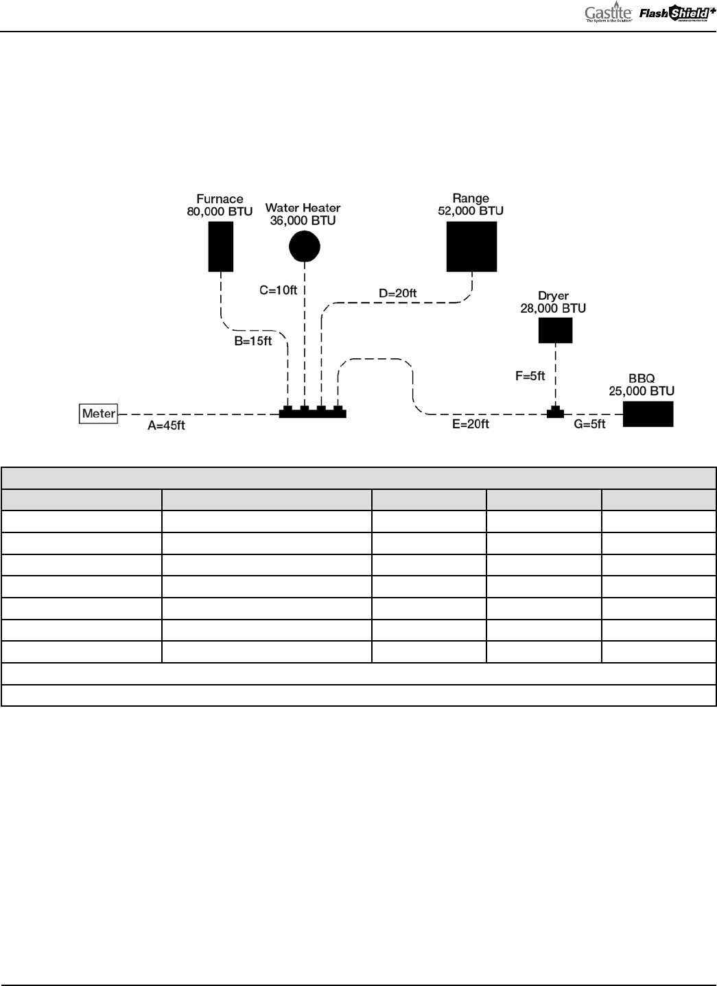
GASTITE DIVISION, TITEFLEX CORPORATION / 1116 Vaughn Parkway / Portland, TN 37148
800.662.0208 / www.gastite.com / [email protected]
25
SECTION 3: SYSTEM CONFIGURATION / JANUARY 2020
3.2.3 EXAMPLE 2: PARALLEL SYSTEM – 6"WC
Figure 3-10 below shows the same house as Example 1. e piping is arranged in parallel fashion, with individual CSST
appliance runs supplied by a main distribution manifold. e utility company’s supply pressure (downstream of the meter)
is 6"WC. e utility company advises that the specific gravity of the gas delivered will be 0.60 and the energy content is 1
CFH = 1000 BTUH. e allowable pressure drop across the system has been determined to be 1.0"WC (supply pressure
6"WC - appliance requirement 5"WC).
Fig. 3-10
TABLE 3-3
SECTION DESCRIPTION LOAD DELIVERED BY SECTION SECTION LENGTH RUN LENGTH TUBE SIZE
“A” – Trunk 221 CFH = 221,000 BTUH 45 feet 70 feet 1" CSST
“B” – Furnace 80 CFH = 80,000 BTUH 15 feet 60 feet 3/4" CSST
“C” – Water Heater 36 CFH = 36,000 BTUH 10 feet 55 feet 1/2" CSST
“D” – Range 52 CFH = 52,000 BTUH 20 feet 65 feet 3/4" CSST
“E” – Dryer/BBQ Trunk 53 CFH = 53,000 BTUH 20 feet 70 feet 3/4" CSST
“F” – Dryer 28 CFH = 28,000 BTUH 5 feet 70 feet 1/2" CSST
“G” – BBQ 25 CFH = 25,000 BTUH 5 feet 70 feet 1/2" CSST
Run Length for Trunk Sections = Distance from meter to furthest appliance (Longest Run)
Run Length for Appliance Sections = Distance from meter to each appliance
SIZING RUN “A”
• Run “A” is sized by the total load of all appliances and the run length from the meter to the furthest appliance
• e total load of all appliances is 80 + 36 + 52 + 28 + 25 = 221CFH
• e run length to the BBQ (furthest appliance) is 45 + 20 + 5 = 70ft
• Referring to Table 7-2 (1.0"WC pressure drop): for a 70ft run, 1" CSST has a capacity over 221CFH (actual: 227)
SIZING RUN “B”
• Run “B” is sized by the load of the supplied appliance and the run length from the meter to the supplied appliance
• e load of the furnace is 80CFH
• e run length to the furnace is 45 + 15 = 60ft
• Referring to Table 7-2 (1.0"WC pressure drop) for a 60ft run, 3/4" CSST has a capacity over 80CFH (actual: 110)

GASTITE DIVISION, TITEFLEX CORPORATION / 1116 Vaughn Parkway / Portland, TN 37148
800.662.0208 / www.gastite.com / [email protected]
26
SECTION 3: SYSTEM CONFIGURATION / JANUARY 2020
SIZING RUN “C”
• Run “C” is sized by the load of the supplied appliance and the run length to the supplied appliance
• e load of the water heater is 36CFH
• e run length to the water heater is 45 + 10 = 55ft
• Referring to Table 7-2 (1.0"WC pressure drop) for a 60ft run, 1/2" CSST has a capacity over 36CFH (actual: 54)
SIZING RUN “D”
• Run “D” is sized by the load of the supplied appliance and the run length to the supplied appliance
• e load of the range is 52CFH
• e run length to the range is 45 + 20 = 65ft
• Referring to Table 7-2 (1.0"WC pressure drop) for a 70ft run, 3/4" CSST has a capacity over 52CFH (actual: 103)
SIZING RUN “E”
• Run “E” is sized by the total load of all supplied appliances and the run length from the meter to the furthest appliance
• e total load of the BBQ and the dryer is 25 + 28 = 53CFH
• e run length to the BBQ (furthest appliance) is 45 + 20 + 5 = 70ft
• Referring to Table 7-2 (1.0"WC pressure drop) for a 70ft run, 3/4" CSST has a capacity over 53CFH (actual: 103)
SIZING RUN “F”
• Run “F” is sized by the load of the supplied appliance and the run length to the supplied appliance
• e load of the dryer is 28CFH
• e run length to the dryer is 45 + 20 + 5 = 70ft
• Referring to Table 7-2 (1.0"WC pressure drop) for a 70ft run, 1/2" CSST has a capacity over 28CFH (actual: 50)
SIZING RUN “G”
• Run “G” is sized by the total load of the supplied appliance and the run length from the meter to the furthest appliance
• e load of the BBQ is 25CFH
• e run length to the BBQ is 45 + 20 + 5 = 70ft
• Referring to Table 7-2 (1.0"WC pressure drop) for a 70ft run, 1/2" CSST has a capacity over 25CFH (actual: 50)
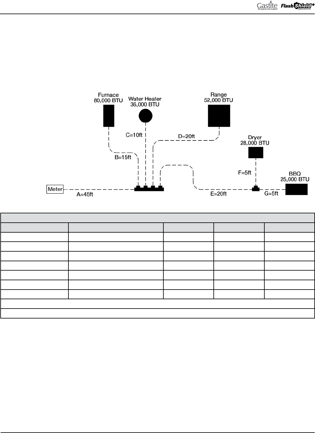
GASTITE DIVISION, TITEFLEX CORPORATION / 1116 Vaughn Parkway / Portland, TN 37148
800.662.0208 / www.gastite.com / [email protected]
27
SECTION 3: SYSTEM CONFIGURATION / JANUARY 2020
3.2.4 EXAMPLE 3: PARALLEL SYSTEM – 12-14"WC
Figure 3-11 below shows the same house and piping system as Example 2. e piping is arranged in parallel fashion,
with individual CSST appliance runs supplied by a main distribution manifold. e utility company’s supply pressure
(downstream of the meter) is 12-14"WC. e utility company advises that the specific gravity of the gas delivered will be
0.60 and the energy content is 1 CFH = 1000 BTUH. e allowable pressure drop across the system has been determined
to be 7"WC (supply pressure 12"WC - appliance requirement 5"WC). As there is no 7"WC pressure drop chart available
we must use the next lowest chart: in this case the 6"WC pressure drop chart (Table 7-8).
Fig. 3-11
TABLE 3-4
SECTION DESCRIPTION LOAD DELIVERED BY SECTION SECTION LENGTH RUN LENGTH TUBE SIZE
“A” – Trunk 221 CFH = 221,000 BTUH 45 feet 70 feet 3/4" CSST
“B” – Furnace 80 CFH = 80,000 BTUH 15 feet 60 feet 1/2" CSST
“C” – Water Heater 36 CFH = 36,000 BTUH 10 feet 55 feet 3/8" CSST
“D” – Range 52 CFH = 52,000 BTUH 20 feet 65 feet 1/2" CSST
“E” – Dryer/BBQ Trunk 53 CFH = 53,000 BTUH 20 feet 70 feet 1/2" CSST
“F” – Dryer 28 CFH = 28,000 BTUH 5 feet 70 feet 3/8" CSST
“G” – BBQ 25 CFH = 25,000 BTUH 5 feet 70 feet 3/8" CSST
Run Length for Trunk Sections = Distance from meter to furthest appliance (Longest Run)
Run Length for Appliance Sections = Distance from meter to each appliance
SIZING RUN “A”
• Run “A” is sized by the total load of all appliances and the run length from the meter to the furthest appliance
• e total load of all appliances is 80 + 36 + 52 + 28 + 25 = 221CFH
• e run length to the BBQ (furthest appliance) is 45 + 20 + 5 = 70ft
• Referring to Table 7-8 (6.0"WC pressure drop) for a 70ft run, 3/4" CSST has a capacity over 221CFH (actual: 234)
SIZING RUN “B”
• Run “B” is sized by the load of the supplied appliance and the run length from the meter to the supplied appliance
• e load of the furnace is 80CFH
• e run length to the furnace is 45 + 15 = 60ft
• Referring to Table 7-8 (6.0"WC pressure drop) for a 60ft run, 1/2" CSST has a capacity over 80CFH (actual: 131)

GASTITE DIVISION, TITEFLEX CORPORATION / 1116 Vaughn Parkway / Portland, TN 37148
800.662.0208 / www.gastite.com / [email protected]
28
SECTION 3: SYSTEM CONFIGURATION / JANUARY 2020
SIZING RUN “C”
• Run “C” is sized by the load of the supplied appliance and the run length to the supplied appliance
• e load of the water heater is 36CFH
• e run length to the water heater is 45 + 10 = 55ft
• Referring to Table 7-8 (6.0"WC pressure drop) for a 60ft run, 3/8" CSST has a capacity over 36CFH (actual: 47)
SIZING RUN “D”
• Run “D” is sized by the load of the supplied appliance and the run length to the supplied appliance
• e load of the range is 52CFH
• e run length to the range is 45 + 20 = 65ft
• Referring to Table 7-8 (6.0"WC pressure drop) for a 70ft run, 1/2" CSST has a capacity over 52CFH (actual: 122)
SIZING RUN “E”
• Run “E” is sized by the total load of all supplied appliances and the run length from the meter to the furthest appliance
• e total load of the BBQ and the dryer is 25 + 28 = 53CFH
• e run length to the BBQ (furthest appliance) is 45 + 20 + 5 = 70ft
• Referring to Table 7-8 (6.0"WC pressure drop) for a 70ft run, 1/2" CSST has a capacity over 53CFH (actual: 122)
SIZING RUN “F”
• Run “F” is sized by the load of the supplied appliance and the run length to the supplied appliance
• e load of the dryer is 28CFH
• e run length to the dryer is 45 + 20 + 5 = 70ft
• Referring to Table 7-8 (6.0"WC pressure drop) for a 70ft run, 3/8" CSST has a capacity over 28CFH (actual: 43)
SIZING RUN “G”
• Run “G” is sized by the total load of the supplied appliance and the run length from the meter to the furthest appliance
• e load of the BBQ is 25CFH
• e run length to the BBQ is 45 + 20 + 5 = 70ft
• Referring to Table 7-8 (6.0"WC pressure drop) for a 70ft run, 3/8" CSST has a capacity over 25CFH (actual: 43)
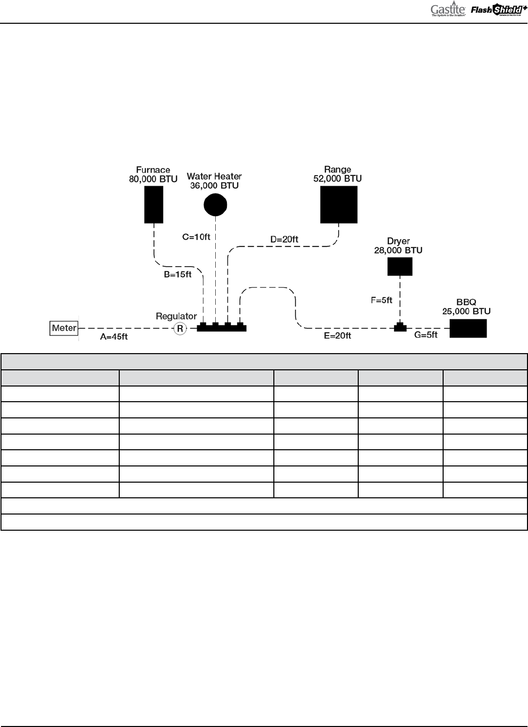
GASTITE DIVISION, TITEFLEX CORPORATION / 1116 Vaughn Parkway / Portland, TN 37148
800.662.0208 / www.gastite.com / [email protected]
29
SECTION 3: SYSTEM CONFIGURATION / JANUARY 2020
3.2.5 EXAMPLE 4: DUAL PRESSURE SYSTEM – 2 PSI TRUNK AND 8"WC APPLIANCE RUNS
Figure 3-12 below shows the same house and similar piping system as Example 3. e piping is arranged in parallel fashion,
with individual CSST appliance runs supplied by a main distribution manifold. A regulator is mounted at the manifold. e
utility company’s supply pressure (downstream of the meter) is 2 PSI. e utility company advises that the specific gravity
of the gas delivered will be 0.60 and the energy content is 1 CFH = 1000 BTUH. e pounds-to-inches regulator is set to
8"WC. Downstream of the regulator the allowable pressure drop across the system has been determined to be 3"WC (supply
pressure 8"WC - appliance requirement 5"WC). Upstream of the regulator the 2 PSI line pressure chart with a pressure drop
of 1 PSI can be used. is will supply the regulator with the 1 PSI inlet pressure required for full capacity flow.
Fig. 3-12
TABLE 3-5
SECTION DESCRIPTION LOAD DELIVERED BY SECTION SECTION LENGTH RUN LENGTH TUBE SIZE
“A” – Trunk 221 CFH = 221,000 BTUH 45 feet 45 feet 1/2" CSST
“B” – Furnace 80 CFH = 80,000 BTUH 15 feet 15 feet 1/2" CSST
“C” – Water Heater 36 CFH = 36,000 BTUH 10 feet 10 feet 3/8" CSST
“D” – Range 52 CFH = 52,000 BTUH 20 feet 20 feet 3/8" CSST
“E” – Dryer/BBQ 53 CFH = 53,000 BTUH 20 feet 25 feet 1/2" CSST
“F” – Dryer 28 CFH = 28,000 BTUH 5 feet 25 feet 3/8" CSST
“G” – BBQ 25 CFH = 25,000 BTUH 5 feet 25 feet 3/8" CSST
Run Length for Trunk Sections = Distance from meter to regulator
Run Length for Appliance Sections = Distance from regulator to each appliance
SIZING RUN “A”
• Run “A” is sized by the total load of all appliances and the run length from the meter to the regulator
• e total load of all appliances is 80 + 36 + 52 + 28 + 25 = 221CFH
• e run length to the regulator is 45ft
• Referring to Table 7-10 (2 PSI line pressure, 1 PSI pressure drop) for a 45ft run, 1/2" CSST has a capacity over 221CFH
(actual: 307)
SIZING RUN “B”
• Run “B” is sized by the load of the supplied appliance and the run length from the regulator to the supplied appliance
• e load of the furnace is 80CFH
• e run length to the furnace is 15ft
• Referring to Table 7-5 (3.0"WC pressure drop) for a 15ft run, 1/2" CSST has a capacity over 80CFH (actual: 185)

GASTITE DIVISION, TITEFLEX CORPORATION / 1116 Vaughn Parkway / Portland, TN 37148
800.662.0208 / www.gastite.com / [email protected]
30
SECTION 3: SYSTEM CONFIGURATION / JANUARY 2020
SIZING RUN “C”
• Run “C” is sized by the load of the supplied appliance and the run length to the supplied appliance
• e load of the water heater is 36CFH
• e run length to the water heater is 10ft
• Referring to Table 7-5 (3.0"WC pressure drop) for a 10ft run, 3/8" CSST has a capacity over 36CFH (actual: 83)
SIZING RUN “D”
• Run “D” is sized by the load of the supplied appliance and the run length to the supplied appliance
• e load of the range is 52CFH
• e run length to the range is 20ft
• Referring to Table 7-5 (3.0"WC pressure drop) for a 20ft run, 3/8" CSST has a capacity over 52CFH (actual: 58)
SIZING RUN “E”
• Run “E” is sized by the total load of all supplied appliances and the run length from the regulator to the furthest appliance
• e total load of the BBQ and the dryer is 25 + 28 = 53CFH
• e run length to the BBQ (furthest appliance) is 20 + 5 = 25ft
• Referring to Table 7-5 (3.0"WC pressure drop) for a 25ft run, 1/2" CSST has a capacity over 53CFH (actual: 144)
SIZING RUN “F”
• Run “F” is sized by the load of the supplied appliance and the run length to the supplied appliance
• e load of the dryer is 28CFH
• e run length to the dryer is 20 + 5 = 25ft
• Referring to Table 7-5 (3.0"WC pressure drop) for a 25ft run, 3/8" CSST has a capacity over 28CFH (actual: 51)
SIZING RUN “G”
• Run “G” is sized by the total load of the supplied appliance and the run length from the regulator to the furthest appliance
• e load of the BBQ is 25CFH
• e run length to the BBQ is 20 + 5 = 25ft
• Referring to Table 7-5 (3.0"WC pressure drop) for a 25ft run, 3/8" CSST has a capacity over 25CFH (actual: 51)
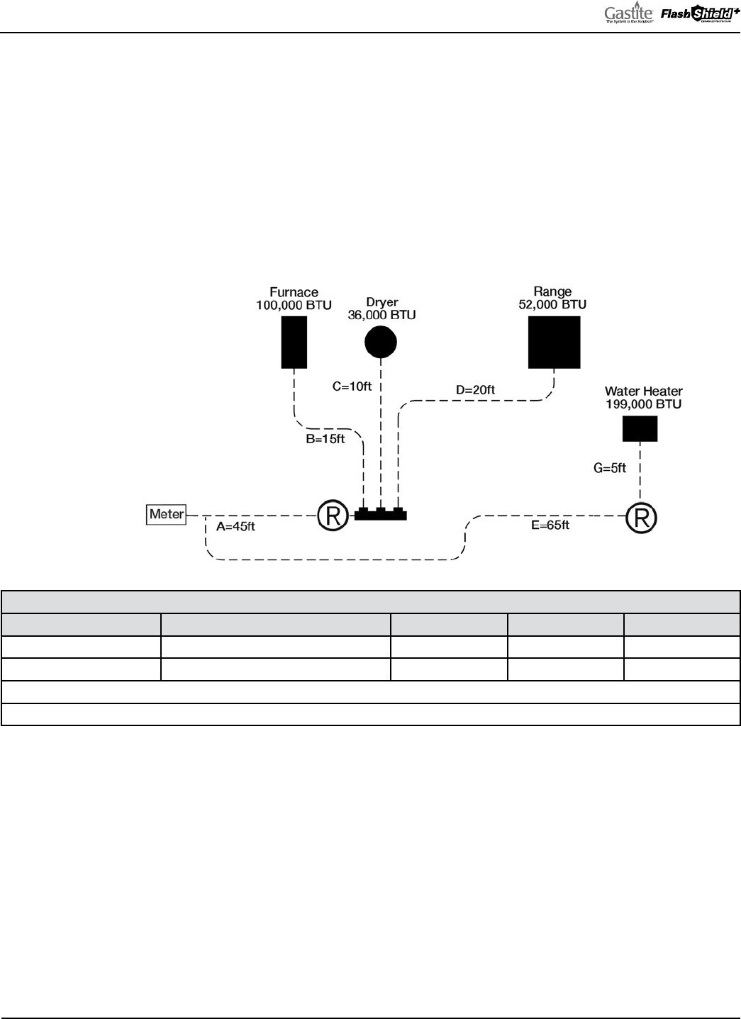
GASTITE DIVISION, TITEFLEX CORPORATION / 1116 Vaughn Parkway / Portland, TN 37148
800.662.0208 / www.gastite.com / [email protected]
31
SECTION 3: SYSTEM CONFIGURATION / JANUARY 2020
3.2.6 EXAMPLE 5: TANKLESS SIZING SYSTEM
e figure below shows an installation of an instantaneous water heater where a new dedicated gas line is run from the
meter. e utility company’s supply pressure (downstream of the meter) is 2 PSI. e utility company advises that the
specific gravity of the gas delivered will be 0.06 and the energy content is 1 CFH =1000 BTUH. e pounds-to-inches
regulators are set to 8"WC. Downstream of the regulators the allowable pressure drop across the system has been
determined to be 3"WC (supply pressure 8"WC – appliance requirement 5"WC) Upstream of the regulators the 2 PSI
line pressure chart with a pressure drop of 1 PSI can be used. is will supply the regulators with the 1 PSI inlet pressure
required for full capacity flow.
To size the elevated pressure trunk lines, use the Longest Run Method to determine the trunk line by using the distance
from the meter to each regulator.
Fig. 3-13
TABLE 3-6
SECTION DESCRIPTION LOAD DELIVERED BY SECTION SECTION LENGTH RUN LENGTH TUBE SIZE
“A” – Trunk 188 CFH = 188,000 BTUH 45 feet 45 feet 1/2" CSST
“E” – Trunk 199 CFH = 199,000 BTUH 65 feet 65 feet 1/2" CSST
Longest Run for Trunk Section = Distance from meter to furthest regulator.
Appliance runs are determined using the length and load for each section only.
SIZING RUN “A”
• Run “A” is sized by the load of all appliances and the run length from the meter to the farthest regulator
• e total load of all appliances is 100+36+52 = 188 CFH
• e run length to the regulator is 45 ft
• Referring to Table 7-10 (
2 PSI with a 1 PSI drop): for a 45-ft run, 1/2" CSST has a capacity over 188 CFH (307 actual)
SIZING RUN “E”
• Run “E” is sized by the load of all appliances and the run length from the meter to the farthest regulator
• e total load of all appliances is 199 = 199 CFH
• e run length to the regulator is 65 ft
• Referring to Table 7-10 (2 PSI with a 1 PSI drop): for a 70-ft run, 1/2" CSST has a capacity over 199 CFH (260 actual)
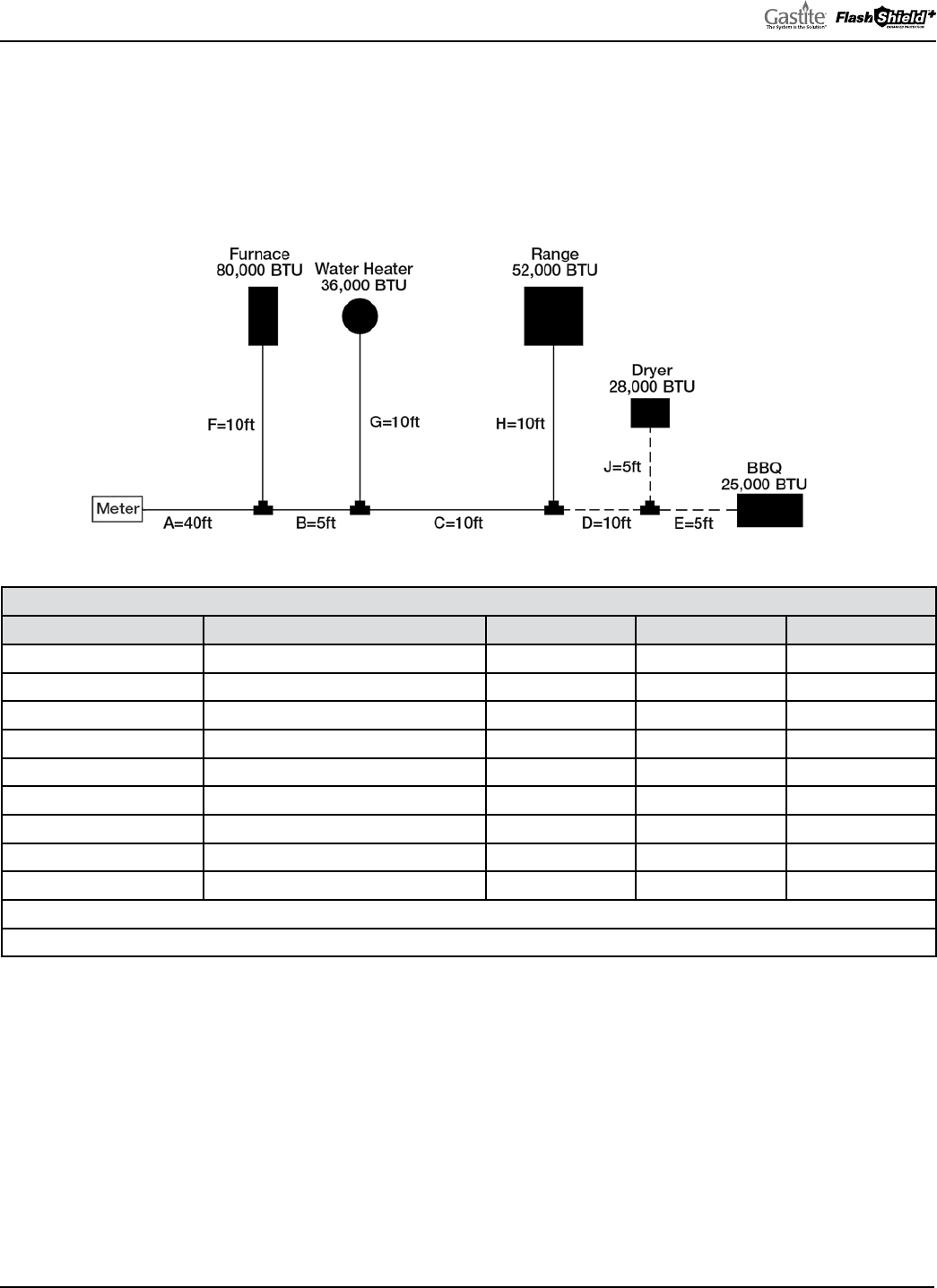
GASTITE DIVISION, TITEFLEX CORPORATION / 1116 Vaughn Parkway / Portland, TN 37148
800.662.0208 / www.gastite.com / [email protected]
32
SECTION 3: SYSTEM CONFIGURATION / JANUARY 2020
3.2.7 EXAMPLE 6: SERIES SYSTEM – 7"WC - HYBRID
Figure 3-14 below shows a typical single-family house retrofit installation with five (5) appliances, 2 of which are added
onto an existing black pipe system. e piping is arranged in series with a main run branching at the appliances. e utility
company’s supply pressure (downstream of the meter) is 7"WC. e utility company advises that the specific gravity of the
gas delivered will be 0.60 and the energy content is 1 CFH = 1000 BTUH. e allowable pressure drop across the system
has been determined to be 2.0"WC (supply pressure 7"WC - appliance requirement 5"WC).
Note: Rigid pipe sized using a 0.5"WC pressure drop table, as no 2.0"WC pressure drop table for Rigid pipe is available.
TABLE 3-7
SECTION DESCRIPTION LOAD DELIVERED BY SECTION SECTION LENGTH RUN LENGTH TUBE SIZE
“A” – Rigid Trunk 221 CFH = 221,000 BTUH 40 feet 70 feet 1" Rigid
“B” – Rigid Trunk 141 CFH = 140,000 BTUH 5 feet 70 feet 1" Rigid
“C” – Rigid Trunk 105 CFH = 105,000 BTUH 10 feet 70 feet 3/4" Rigid
“D” – CSST Trunk 53 CFH = 53,000 BTUH 10 feet 70 feet 1/2" CSST
“E” – BBQ 25 CFH = 25,000 BTUH 5 feet 70 feet 1/2" CSST
“F” – Furnace 80 CFH = 80,000 BTUH 10 feet 50 feet 3/4" Rigid
“G” – Water Heater 36 CFH = 36,000 BTUH 10 feet 55 feet 3/8" Rigid
“H” – Range 52 CFH = 52,000 BTUH 10 feet 65 feet 1/2" Rigid
“J” – Dryer 28 CFH = 28,000 BTUH 5 feet 70 feet 1/2" CSST
Run Length for Trunk Sections = Distance from meter to furthest appliance (Longest Run)
Run Length for Appliance Sections = Distance from meter to each appliance
SIZING RUN “A”
• Run “A” is sized by the total load of all appliances and the run length from the meter to the furthest appliance
• e total load of all appliances is 80 + 36 + 52 + 28 + 25 = 221CFH
• e run length to the BBQ (furthest appliance) is 40 + 5 + 10 + 10 + 5 = 70ft
• Referring to Table 7-23 (Rigid pipe 0.5"WC pressure drop): for a 70ft run, 1" Rigid pipe has a capacity over 221CFH
(actual: 240)
SIZING RUN “B”
• Run “B” is sized by the total load of all supplied appliances and the run length from the meter to the furthest appliance
• e total load of the supplied appliances is 36 + 52 + 28 + 25 = 141CFH
• e run length to the BBQ (furthest appliance) is 40 + 5 + 10 + 10 + 5 = 70ft
• Referring to Table 7-23 (Rigid pipe 0.5"WC pressure drop) for a 70ft run, 1" Rigid pipe has a capacity over 141CFH
(actual: 240)
Fig. 3-14

GASTITE DIVISION, TITEFLEX CORPORATION / 1116 Vaughn Parkway / Portland, TN 37148
800.662.0208 / www.gastite.com / [email protected]
33
SECTION 3: SYSTEM CONFIGURATION / JANUARY 2020
SIZING RUN “C”
• Run “C” is sized by the total load of all supplied appliances and the run length from the meter to the furthest appliance
• e total load of all appliances is 52 + 28 + 25 = 105CFH
• e run length to the BBQ (furthest appliance) is 40 + 5 + 10 + 10 + 5 = 70ft
• Referring to Table 7-23 (Rigid pipe 0.5"WC pressure drop): for a 70ft run, 3/4" Rigid pipe has a capacity over 105CFH
(actual: 125)
SIZING RUN “D”
• Run “D” is sized by the total load of all supplied appliances and the run length from the meter to the furthest appliance
• e total load of the BBQ and the dryer is 25 + 28 = 53CFH
• e run length to the BBQ (furthest appliance) is 40 + 5 + 10 + 10 + 5 = 70ft
• Referring to Table 7-4 (2.0"WC pressure drop) for a 70ft run, 1/2" CSST has a capacity over 53CFH (actual: 71)
SIZING RUN “E”
• Run “E” is sized by the total load of the supplied appliance and the run length from the meter to the furthest appliance
• e load of the BBQ is 25CFH
• e run length to the BBQ is 40 + 5 + 10 + 10 + 5 = 70ft
• Referring to Table 7-4 (2.0"WC pressure drop) for a 70ft run, 1/2" CSST has a capacity over 25CFH (actual: 71)
SIZING RUN “F”
• Run “F” is sized by the load of the supplied appliance and the run length from the meter to the supplied appliance
• e load of the furnace is 80CFH
• e run length to the furnace is 40 + 10 = 50ft
• Referring to Table 7-23 (Rigid pipe 0.5"WC pressure drop) for a 50ft run, 3/4" Rigid pipe has a capacity over 80CFH
(actual: 151)
SIZING RUN “G”
• Run “G” is sized by the load of the supplied appliance and the run length to the supplied appliance
• e load of the water heater is 36CFH
• e run length to the water heater is 40 + 5 + 10 = 55ft
• Referring to Table 7-23 (Rigid pipe 0.5"WC pressure drop) for a 60ft run, 3/8" Rigid pipe has a capacity over 36CFH (actual: 36)
SIZING RUN “H”
• Run “H” is sized by the load of the supplied appliance and the run length to the supplied appliance
• e load of the range is 52CFH
• e run length to the range is 40 + 5 + 10 + 10 = 65ft
• Referring to Table 7-23 (Rigid pipe 0.5"WC pressure drop) for a 70ft run, 1/2" Rigid pipe has a capacity over 52CFH (actual: 61)
SIZING RUN “J”
• Run “J” is sized by the load of the supplied appliance and the run length to the supplied appliance
• e load of the dryer is 28CFH
• e run length to the dryer is 40 + 5 + 10 + 10 + 5 = 70ft
• Referring to Table 7-4 (2.0"WC pressure drop) for a 70ft run, 1/2" CSST has a capacity over 28CFH (actual: 71)
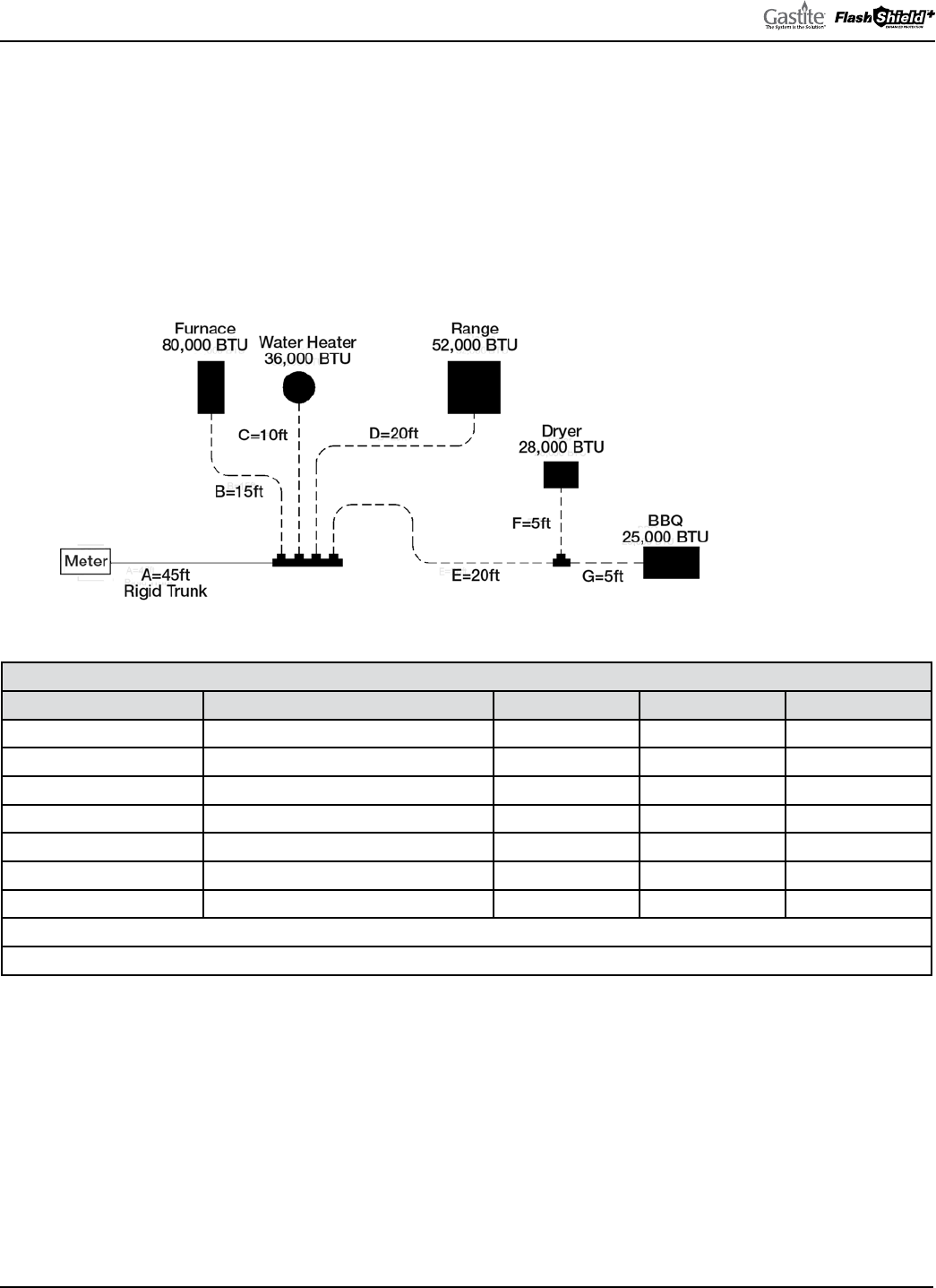
GASTITE DIVISION, TITEFLEX CORPORATION / 1116 Vaughn Parkway / Portland, TN 37148
800.662.0208 / www.gastite.com / [email protected]
34
SECTION 3: SYSTEM CONFIGURATION / JANUARY 2020
3.2.8 EXAMPLE 7: PARALLEL SYSTEM – 7"WC – HYBRID
Figure 3-15 below shows the same house and similar piping system as Example 2. e piping is arranged in parallel
fashion, with individual CSST appliance runs supplied by a main distribution manifold. e main trunk line (“A”) from
the meter to the distribution manifold is rigid pipe rather than CSST. e utility company’s supply pressure (downstream
of the meter) is 7"WC. e utility company advises that the specific gravity of the gas delivered will be 0.60 and the energy
content is 1 CFH = 1000 BTUH.
e allowable pressure drop across the system has been determined to be 2"WC (supply pressure 7"WC - appliance
requirement 5"WC). 0.5"WC pressure drop will be taken over the rigid pipe trunk line and the remaining appliance runs.
Fig. 3-15
Note: Rigid pipe sized using a 0.5"WC pressure drop table, as no 2.0"WC pressure drop table for Rigid pipe is available.
TABLE 3-8
SECTION DESCRIPTION LOAD DELIVERED BY SECTION SECTION LENGTH RUN LENGTH TUBE SIZE
“A” – Rigid Trunk 221 CFH = 221,000 BTUH 45 feet 70feet 1" Rigid
“B” – Furnace 80 CFH = 80,000 BTUH 15 feet 60 feet 3/4" CSST
“C” – Water Heater 36 CFH = 36,000 BTUH 10 feet 55 feet 1/2" CSST
“D” – Range 52 CFH = 52,000 BTUH 20 feet 65 feet 1/2" CSST
“E” – Dryer/BBQ Trunk 53 CFH = 53,000 BTUH 20 feet 70 feet 1/2" CSST
“F” – Dryer 28 CFH = 28,000 BTUH 5 feet 70 feet 1/2" CSST
“G” – BBQ 25 CFH = 25,000 BTUH 5 feet 70 feet 1/2" CSST
Run Length for Trunk Sections = Distance from meter to furthest appliance (Longest Run)
Run Length for Appliance Sections = Distance from meter to each appliance
SIZING RUN “A”
• Run “A” is sized by the total load of all appliances and the run length from the meter to the furthest appliance
• e total load of all appliances is 80 + 36 + 52 + 28 + 25 = 221CFH
• e run length to the BBQ (furthest appliance) is 45 + 20 + 5 = 70ft
• Referring to Table 7-23 (Rigid pipe 0.5"WC pressure drop): for a 70ft run, 1" pipe has a capacity over 221CFH (actual: 240)
SIZING RUN “B”
• Run “B” is sized by the load of the supplied appliance and the run length from the meter to the supplied appliance
• e load of the furnace is 80CFH
• e run length to the furnace is 45 + 15 = 60ft
• Referring to Table 7-4 (2.0"WC pressure drop) for a 60ft run, 3/4" CSST has a capacity over 80CFH (actual: 152)

GASTITE DIVISION, TITEFLEX CORPORATION / 1116 Vaughn Parkway / Portland, TN 37148
800.662.0208 / www.gastite.com / [email protected]
35
SECTION 3: SYSTEM CONFIGURATION / JANUARY 2020
SIZING RUN “C”
• Run “C” is sized by the load of the supplied appliance and the run length from the meter to the supplied appliance
• e load of the water heater is 36CFH
• e run length to the water heater is 45 + 10 = 55ft
• Referring to Table 7-4 (2.0"WC pressure drop) for a 60ft run, 1/2" CSST has a capacity over 36CFH (actual: 76)
SIZING RUN “D”
• Run “D” is sized by the load of the supplied appliance and the run length from the meter to the supplied appliance
• e load of the range is 52CFH
• e run length to the range is 45 + 20 = 65ft
• Referring to Table 7-4 (2.0"WC pressure drop) for a 70ft run, 1/2" CSST has a capacity over 52CFH (actual: 71)
SIZING RUN “E”
• Run “E” is sized by the total load of all supplied appliances and the run length from the meter to the furthest appliance
• e total load of the BBQ and the dryer is 25 + 28 = 53CFH
• e run length to the BBQ (furthest appliance) is 45 + 20 + 5 = 70ft
• Referring to Table 7-4 (2.0"WC pressure drop) for a 70ft run, 1/2" CSST has a capacity over 53CFH (actual: 71)
SIZING RUN “F”
• Run “F” is sized by the load of the supplied appliance and the run length from the meter to the supplied appliance
• e load of the dryer is 28CFH
• e run length to the dryer is 45 + 20 + 5 = 70ft
• Referring to Table 7-4 (2.0"WC pressure drop) for a 70ft run, 1/2" CSST has a capacity over 28CFH (actual: 71)
SIZING RUN “G”
• Run “G” is sized by the total load of the supplied appliance and the run length from the meter to the furthest appliance
• e load of the BBQ is 25CFH
• e run length to the BBQ is 45 + 20 + 5 = 70ft
• Referring to Table 7-4 (2.0"WC pressure drop) for a 70ft run, 1/2" CSST has a capacity over 25CFH (actual: 71)
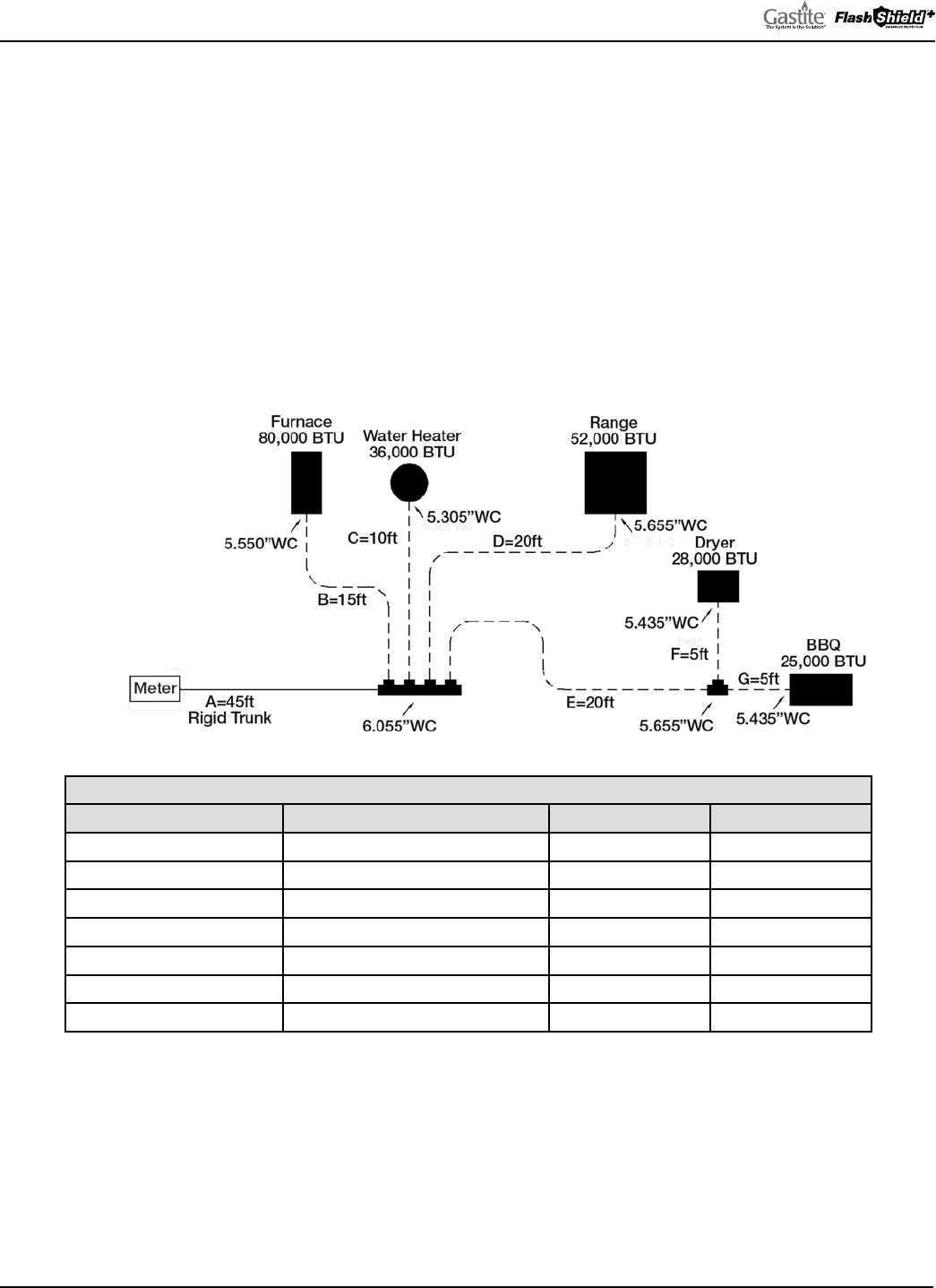
GASTITE DIVISION, TITEFLEX CORPORATION / 1116 Vaughn Parkway / Portland, TN 37148
800.662.0208 / www.gastite.com / [email protected]
36
SECTION 3: SYSTEM CONFIGURATION / JANUARY 2020
3.2.9 EXAMPLE 8: SUMMATION METHOD FOR PARALLEL SYSTEM – 7"WC – HYBRID
Figure 3-16 below shows the same house as Example 6. e piping is arranged in parallel fashion, with individual CSST
appliance runs supplied by a main distribution manifold. e main trunk line (“A”) from the meter to the distribution
manifold is rigid pipe rather than CSST. e utility company’s supply pressure (downstream of the meter) is 7"WC. e
utility company advises that the specific gravity of the gas delivered will be 0.60 and the energy content is 1 CFH = 1000
BTUH. e allowable pressure drop across the system has been determined to be 2.0"WC (supply pressure 7"WC -
appliance requirement 5"WC).
When using the “Summation Method” for gas pipe sizing, the sum of the pressure losses through each section of pipe
should result in a minimum 5"WC pressure delivered to the appliance inlet. (Pressures less than 5"WC may be sufficient
for proper appliance operation but should be reviewed with the manufacturer’s input rating and the local administrative
authority).
Fig. 3-16
TABLE 3-9
SECTION DESCRIPTION LOAD DELIVERED BY SECTION SECTION LENGTH TUBE SIZE
“A” – Rigid Trunk 221 CFH = 221,000 BTUH 45 feet 3/4" Rigid
“B” – Furnace 80 CFH = 80,000 BTUH 15 feet 1/2" CSST
“C” – Water Heater 36 CFH = 36,000 BTUH 10 feet 3/8" CSST
“D” – Range 52 CFH = 52,000 BTUH 20 feet 1/2" CSST
“E” – Dryer/BBQ Trunk 53 CFH = 53,000 BTUH 20 feet 1/2" CSST
“F” – Dryer 28 CFH = 28,000 BTUH 5 feet 3/8" CSST
“G” – BBQ 25 CFH = 25,000 BTUH 5 feet 3/8" CSST
SIZING RUN “A”
• Run “A” is sized by the total load of all appliances and the section length
• e total load of all appliances is 80 + 36 + 52 + 28 + 25 = 221CFH
• e section length is 45ft
• Referring to Table 7-24 (Pressure drop per foot for Rigid Pipe): for a 225CFH load, 3/4" pipe has a drop of 0.021"WC per ft
• e pressure drop over Run “A” is: 0.021" x 45ft = 0.945"WC
• e available pressure at the end of run “A” is 7"WC - 0.945"WC = 6.055"WC

GASTITE DIVISION, TITEFLEX CORPORATION / 1116 Vaughn Parkway / Portland, TN 37148
800.662.0208 / www.gastite.com / [email protected]
37
SECTION 3: SYSTEM CONFIGURATION / JANUARY 2020
SIZING RUN “B”
• Run “B” is sized by the load of the supplied appliance and the section length
• e load of the furnace is 80CFH
• e section length to the furnace is 15ft
• Referring to Table 7-21 (Pressure drop per foot for Gastite® CSST): for a 80CFH load, 1/2" CSST has a drop of 0.037"WC / ft
• e pressure drop over Run “B” is: 0.037" x 15ft = 0.555"WC
• e available pressure at the end of run “B” is 6.055"WC - 0.555"WC = 5.500"WC
SIZING RUN “C”
• Run “C” is sized by the load of the supplied appliance and the section length
• e load of the water heater is 36CFH
• e section length is 10ft
• Referring to Table 7-21 (Pressure drop per foot for Gastite® CSST): for a 40CFH load, 3/8" CSST has a drop of 0.075"WC / ft
• e pressure drop over Run “C” is: 0.075" x 10ft = 0.750"WC
• e available pressure at the end of run “C” is 6.055"WC - 0.750"WC = 5.305"WC
SIZING RUN “D”
• Run “D” is sized by the load of the supplied appliance and the section length
• e load of the range is 52CFH
• e section length is 20ft
• Referring to Table 7-21 (Pressure drop per foot for Gastite® CSST): for a 60CFH load, 1/2" CSST has a drop of 0.020"WC / ft
• e pressure drop over Run “D” is: 0.020" x 20ft = 0.400"WC
• e available pressure at the end of run “D” is 6.055"WC - 0.400"WC = 5.655"WC
SIZING RUN “E”
• Run “E” is sized by the total load of all supplied appliances and the section length
• e total load of the BBQ and the dryer is 25 + 28 = 53CFH
• e section length is 20ft
• Referring to Table 7-21 (Pressure drop per foot for Gastite® CSST): for a 60CFH load, 1/2" CSST has a drop of 0.020"WC / ft
• e pressure drop over Run “E” is: 0.020" x 20ft = 0.400"WC
• e available pressure at the end of run “E” is 6.055"WC - 0.400"WC = 5.655"WC
SIZING RUN “F”
• Run “F” is sized by the load of the supplied appliance and the section length
• e load of the dryer is 28CFH
• e section length 5ft
• Referring to Table 7-21 (Pressure drop per foot for Gastite® CSST): for a 30CFH load, 3/8" CSST has a drop of 0.044"WC / ft
• e pressure drop over Run “F” is: 0.044" x 5ft = 0.220"WC
• e available pressure at the end of run “F” is 5.655"WC - 0.220"WC = 5.435"WC
SIZING RUN “G”
• Run “G” is sized by the total load of the supplied appliance and the section length
• e load of the BBQ is 25CFH
• e section length 5ft
• Referring to Table 7-21 (Pressure drop per foot for Gastite® CSST): for a 30CFH load, 3/8" CSST has a drop of 0.044"WC / ft
• e pressure drop over Run “G” is: 0.044" x 5ft = 0.220"WC
• e available pressure at the end of run “G” is 5.655"WC - 0.220"WC = 5.435"WC
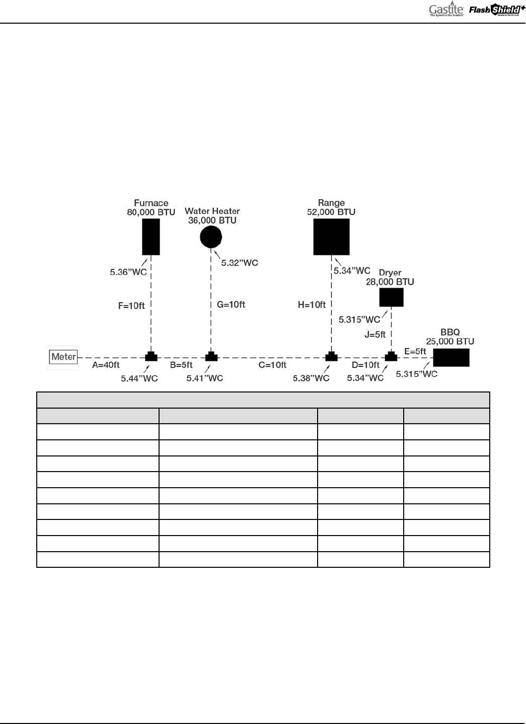
GASTITE DIVISION, TITEFLEX CORPORATION / 1116 Vaughn Parkway / Portland, TN 37148
800.662.0208 / www.gastite.com / [email protected]
38
SECTION 3: SYSTEM CONFIGURATION / JANUARY 2020
3.2.10 EXAMPLE 9: SUMMATION METHOD FOR SERIES SYSTEM – 6"WC
Figure 3-17 below shows the same house and piping system as Example 1. e piping is arranged in series with a main run
branching at the appliances. e utility company’s supply pressure (downstream of the meter) is 6"WC. e utility company
advises that the specific gravity of the gas delivered will be 0.60 and the energy content is 1 CFH = 1000 BTUH. e
allowable pressure drop across the system has been determined to be 1.0"WC (supply pressure 6"WC - appliance requirement
5"WC).
When using the “Summation Method” for gas pipe sizing, the sum of the pressure losses through each section of pipe should
result in a minimum 5"WC pressure delivered to the appliance inlet. (Pressures less than 5"WC may be sufficient for proper
appliance operation but should be reviewed with the manufacturer’s input rating and the local administrative authority).
Fig. 3-17
TABLE 3-10
Section Description Load Delivered by Section Section Length Tube Size
“A” – Trunk 221 CFH = 221,000 BTUH 40 feet 1" CSST
“B” – Trunk 141 CFH = 141,000 BTUH 5 feet 1" CSST
“C” – Trunk 105 CFH = 105,000 BTUH 10 feet 1" CSST
“D” – Trunk 53 CFH = 53,000 BTUH 10 feet 3/4" CSST
“E” – BBQ 25 CFH = 25,000 BTUH 5 feet 1/2" CSST
“F” – Furnace 80 CFH = 80,000 BTUH 10 feet 3/4" CSST
“G” – Water Heater 36 CFH = 36,000 BTUH 10 feet 1/2" CSST
“H” – Range 52 CFH = 52,000 BTUH 10 feet 3/4" CSST
“J” – Dryer 28 CFH = 28,000 BTUH 5 feet 1/2" CSST
SIZING RUN “A”
• Run “A” is sized by the total load of all appliances and the section length
• e total load of all appliances is 80 + 36 + 52 + 28 + 25 = 221CFH
• e section length is 40ft
• Referring to Table 7-21 (Pressure drop per foot for Gastite® CSST): for a 225CFH load, 1" CSST has a drop of 0.014"WC per ft. e
pressure drop over Run “A” is: 0.014" x 40ft = 0.560"WC
• e available pressure at the end of run “A” is 6"WC - 0.560"WC = 5.440"WC

GASTITE DIVISION, TITEFLEX CORPORATION / 1116 Vaughn Parkway / Portland, TN 37148
800.662.0208 / www.gastite.com / [email protected]
39
SECTION 3: SYSTEM CONFIGURATION / JANUARY 2020
SIZING RUN “B”
• Run “B” is sized by the total load of all supplied appliances and the section length
• e total load of the supplied appliances is 36 + 52 + 28 + 25 = 141CFH
• e section length is 5ft
• Referring to Table 7-21 (Pressure drop per foot for Gastite® CSST): for a 150CFH load, 1" CSST has a drop of 0.006"WC / ft
• e pressure drop over Run “B” is: 0.006" x 5ft = 0.030"WC
• e available pressure at the end of run “B” is 5.440"WC - 0.030"WC = 5.410"WC
SIZING RUN “C”
• Run “C” is sized by the total load of all supplied appliances and the section length
• e total load of the supplied appliances is 52 + 28 + 25 = 105CFH
• e section length is 10ft
• Referring to Table 7-21 (Pressure drop per foot for Gastite® CSST): for a 110CFH load, 1" CSST has a drop of 0.003"WC / ft
• e pressure drop over Run “C” is: 0.003" x 10ft = 0.030"WC
• e available pressure at the end of run “C” is 5.410"WC - 0.030"WC = 5.380"WC
SIZING RUN “D”
• Run “D” is sized by the total load of all supplied appliances and the section length
• e total load of the BBQ and the dryer is 25 + 28 = 53CFH
• e section length 10ft
• Referring to Table 7-21 (Pressure drop per foot for Gastite® CSST): for a 60CFH load, 3/4" CSST has a drop of 0.004"WC / ft
• e pressure drop over Run “D” is: 0.004" x 10ft = 0.040"WC
• e available pressure at the end of run “D” is 5.380"WC - 0.040"WC = 5.340"WC
SIZING RUN “E”
• Run “E” is sized by the load of the supplied appliance and the section length
• e load of the BBQ is 25CFH
• e section length is 5ft
• Referring to Table 7-21 (Pressure drop per foot for Gastite® CSST): for a 30CFH load, 1/2" CSST has a drop of 0.005"WC / ft
• e pressure drop over Run “E” is: 0.005" x 5ft = 0.025"WC
• e available pressure at the end of run “E” is 5.340"WC - 0.025"WC = 5.315"WC
SIZING RUN “F”
• Run “F” is sized by the load of the supplied appliance and the section length
• e load of the furnace is 80CFH
• e section length to the furnace is 10ft
• Referring to Table 7-21 (Pressure drop per foot for Gastite® CSST): for a 80CFH load, 3/4" CSST has a drop of 0.008"WC / ft
• e pressure drop over Run “F” is: 0.008" x 10ft = 0.080"WC
• e available pressure at the end of run “F” is 5.440"WC - 0.080"WC = 5.360"WC
SIZING RUN “G”
• Run “G” is sized by the load of the supplied appliance and the section length
• e load of the water heater is 36CFH
• e section length to the water heater is 10ft
• Referring to Table 7-21 (Pressure drop per foot for Gastite® CSST): for a 40CFH load, 1/2" CSST has a drop of 0.009"WC / ft
• e pressure drop over Run “G” is: 0.009" x 10ft = 0.090"WC
• e available pressure at the end of run “G” is 5.410"WC - 0.090"WC = 5.320"WC

GASTITE DIVISION, TITEFLEX CORPORATION / 1116 Vaughn Parkway / Portland, TN 37148
800.662.0208 / www.gastite.com / [email protected]
40
SECTION 3: SYSTEM CONFIGURATION / JANUARY 2020
3.2.10 EXAMPLE 9: SUMMATION METHOD FOR SERIES SYSTEM – 6"WC (CONTINUED)
SIZING RUN “H”
• Run “H” is sized by the load of the supplied appliance and the section length
• e load of the range is 52CFH
• e section length to the range is 10ft
• Referring to Table 7-21 (Pressure drop per foot for Gastite® CSST): for a 60CFH load, 3/4" CSST has a drop of 0.004"WC / ft
• e pressure drop over Run “H” is: 0.004" x 10ft = 0.040"WC
• e available pressure at the end of run “H” is 5.380"WC - 0.040"WC = 5.340"WC
SIZING RUN “J”
• Run “J” is sized by the load of the supplied appliance and the section length
• e load of the dryer is 28CFH
• e section length to the dryer is 5ft
• Referring to Table 7-21 (Pressure drop per foot for Gastite® CSST): for a 30CFH load, 1/2" CSST has a drop of 0.005"WC / ft
• e pressure drop over Run “J” is: 0.005" x 5ft = 0.025"WC
• e available pressure at the end of run “J” is 5.340"WC - 0.025"WC = 5.315"WC
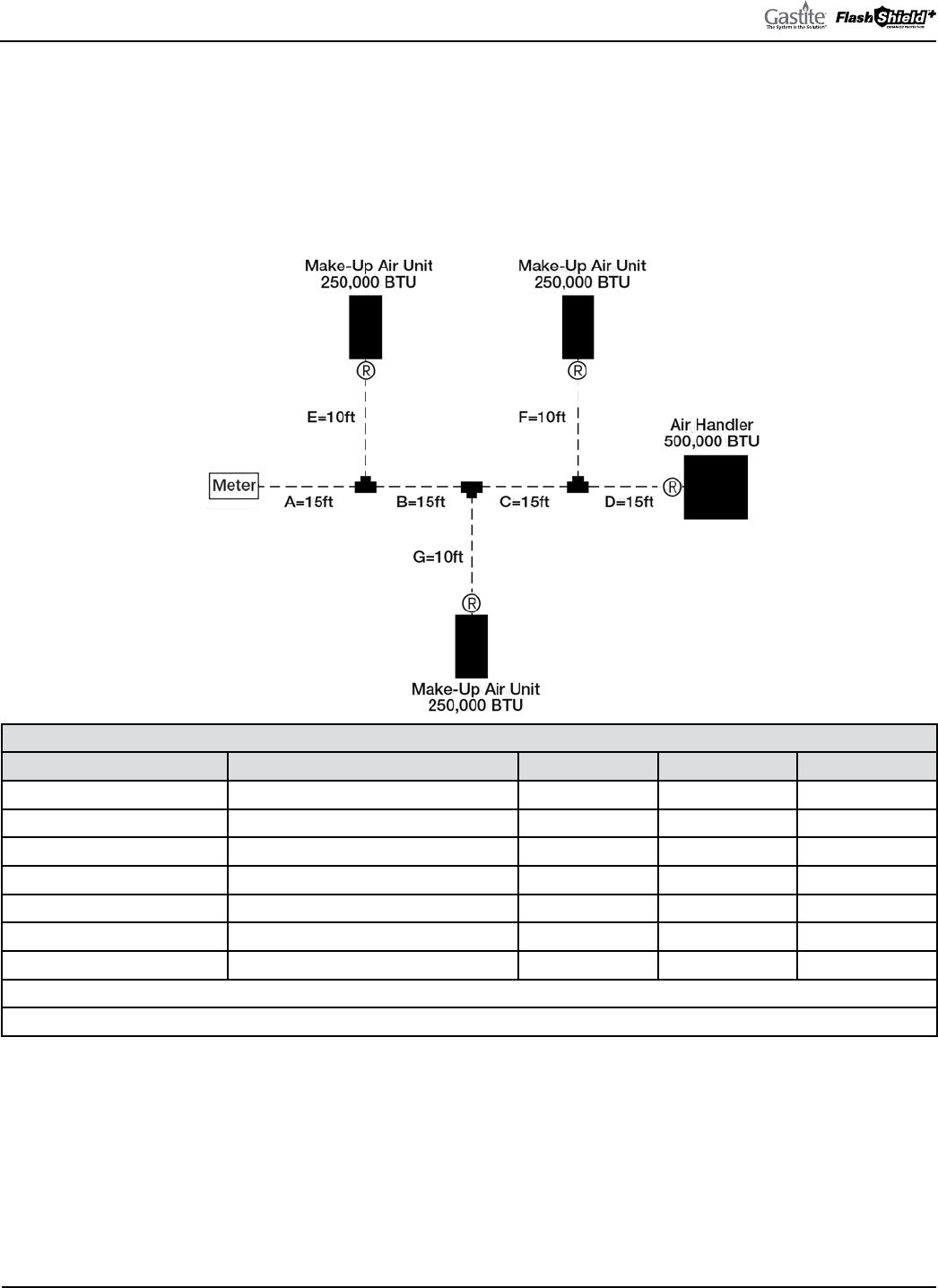
GASTITE DIVISION, TITEFLEX CORPORATION / 1116 Vaughn Parkway / Portland, TN 37148
800.662.0208 / www.gastite.com / [email protected]
41
SECTION 3: SYSTEM CONFIGURATION / JANUARY 2020
3.2.11 EXAMPLE 10: COMMERCIAL ELEVATED PRESSURE SERIES SYSTEM – 2 PSI
Figure 3-18 below shows a typical commercial rooftop installation with four (4) appliances. e piping is arranged in series
with a main run branching at the appliances. e utility company’s supply pressure (downstream of the meter) is 2 PSI.
e utility company advises that the specific gravity of the gas delivered will be 0.60 and the energy content is 1 CFH =
1000 BTUH. e 2 PSI line pressure chart with a pressure drop of 1 PSI can be used. is will supply the regulators with
the 1 PSI inlet pressure required for full capacity flow.
Fig. 3-18
TABLE 3-11
SECTION DESCRIPTION LOAD DELIVERED BY SECTION SECTION LENGTH RUN LENGTH TUBE SIZE
“A” – Trunk 1250 CFH = 1,250,000 BTUH 15 feet 60 feet 1-1/4" CSST
“B” – Trunk 1000 CFH = 1,000,000 BTUH 15 feet 60 feet 1" CSST
“C” – Trunk 750 CFH = 750,000 BTUH 15 feet 60 feet 1" CSST
“D” – Air Handler 500 CFH = 500,000 BTUH 15 feet 60 feet 3/4" CSST
“E” – Make-Up Air Unit 250 CFH = 250,000 BTUH 10 feet 25 feet 1/2" CSST
“F” – Make-Up Air Unit 250 CFH = 250,000 BTUH 10 feet 55 feet 1/2" CSST
“G” – Make-Up Air Unit 250 CFH = 250,000 BTUH 10 feet 40 feet 1/2" CSST
Run Length for Trunk Sections = Distance from meter to furthest appliance (Longest Run)
Run Length for Appliance Sections = Distance from meter to each appliance
SIZING RUN “A”
• Run “A” is sized by the total load of all appliances and the run length from the meter to the furthest appliance
• e total load of all appliances is 250 + 250 + 250 + 500 = 1250CFH
• e run length to the Air Handler (furthest appliance) is 15 + 15 + 15 + 15 = 60ft
• Referring to Table 7-10 (
2 PSI line pressure, 1 PSI pressure drop): for a 60ft run, 1-1/4" CSST has a capacity over 1250CFH
(actual: 1854)

GASTITE DIVISION, TITEFLEX CORPORATION / 1116 Vaughn Parkway / Portland, TN 37148
800.662.0208 / www.gastite.com / [email protected]
42
SECTION 3: SYSTEM CONFIGURATION / JANUARY 2020
SIZING RUN “B”
• Run “B” is sized by the total load of all supplied appliances and the run length from the meter to the furthest appliance
• e total load of the supplied appliances is 250 + 250 + 500 = 1000CFH
• e run length to the Air Handler (furthest appliance) is 15 + 15 + 15 + 15 = 60ft
• Referring to Table 7-10 (2 PSI line pressure, 1 PSI pressure drop): for a 60ft run, 1" CSST has a capacity over 1000CFH
(actual: 1213)
SIZING RUN “C”
• Run “C” is sized by the total load of all supplied appliances and the run length from the meter to the furthest appliance
• e total load of all appliances is 250 + 500 = 750CFH
• e run length to the Air Handler (furthest appliance) is 15 + 15 + 15 + 15 = 60ft
• Referring to Table 7-10 (2 PSI line pressure, 1 PSI pressure drop): for a 60ft run, 1" CSST has a capacity over 750CFH
(actual: 1213)
SIZING RUN “D”
• Run “D” is sized by the total load of all supplied appliances and the run length from the meter to the furthest appliance
• e load of the Air Handler is 500CFH
• e run length to the Air Handler (furthest appliance) is 15 + 15 + 15 + 15 = 60ft
• Referring to Table 7-10 (2 PSI line pressure, 1 PSI pressure drop): for a 60ft run, 3/4" CSST has a capacity over 500CFH
(actual: 510)
SIZING RUN “E”
• Run “E” is sized by the total load of the supplied appliance and the run length from the meter to the supplied appliance
• e load of the Make-Up Air Unit is 250CFH
• e run length to the Make-Up Air Unit is 15 + 10 = 25ft
• Referring to Table 7-10 (2 PSI line pressure, 1 PSI pressure drop): for a 25ft run, 1/2" CSST has a capacity over 250CFH
(actual: 432)
SIZING RUN “F”
• Run “F” is sized by the load of the supplied appliance and the run length from the meter to the supplied appliance
• e load of the Make-Up Air Unit is 250CFH
• e run length to the Make-Up Air Unit is 15 + 15 + 15 + 10 = 55ft
• Referring to Table 7-10 (2 PSI line pressure, 1 PSI pressure drop): for a 60ft run, 1/2" CSST has a capacity over 250CFH
(actual: 281)
SIZING RUN “G”
• Run “G” is sized by the load of the supplied appliance and the run length from the meter to the supplied appliance
• e load of the Make-Up Air Unit is 250CFH
• e run length to the Make-Up Air Unit is 15 + 15 + 10 = 40ft
• Referring to Table 7-10 (2 PSI line pressure, 1 PSI pressure drop): for a 40ft run, 1/2" CSST has a capacity over 250CFH
(actual: 343)
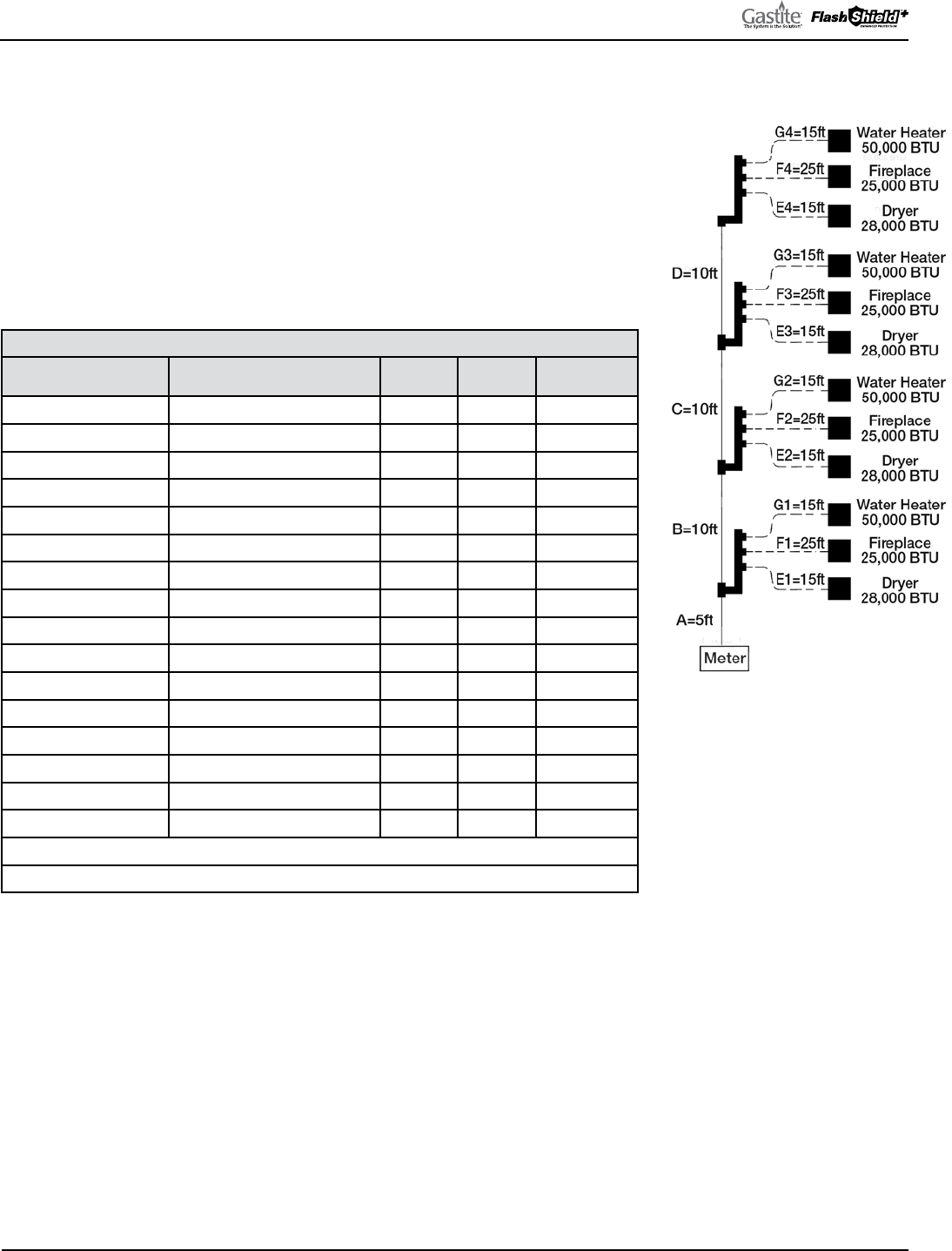
GASTITE DIVISION, TITEFLEX CORPORATION / 1116 Vaughn Parkway / Portland, TN 37148
800.662.0208 / www.gastite.com / [email protected]
43
SECTION 3: SYSTEM CONFIGURATION / JANUARY 2020
3.2.12 EXAMPLE 11: COMMERCIAL HYBRID SYSTEM – 7"WC
Figure 3-19 below shows a multi-level apartment building. e piping is arranged in
vertical parallel fashion, with individual CSST appliance runs supplied by distribution
manifolds. e main trunk line (“A”-“D”) from the meter to the distribution manifolds
is rigid pipe rather than CSST. e utility company’s supply pressure (downstream of
the meter) is 7"WC. e utility company advises that the specific gravity of the gas
delivered will be 0.60 and the energy content is 1 CFH = 1000 BTUH. e allowable
pressure drop across the system has been determined to be 2"WC (supply pressure
7"WC – appliance requirement 5"WC). Note: Rigid pipe sized using a 0.5"WC pressure
drop table as no 2.0"WC pressure drop table for rigid pipe is available.
TABLE 3-12
SECTION DESCRIPTION LOAD DELIVERED BY SECTION
SECTION
LENGTH
RUN
LENGTH
TUBE SIZE
“A” – Rigid Trunk 412 CFH = 412,000 BTUH 5 feet 60 feet 1-1/4" Rigid
“B” – Rigid Trunk 309 CFH = 309,000 BTUH 10 feet 60 feet 1-1/4" Rigid
“C” – Rigid Trunk 206 CFH = 206,000 BTUH 10 feet 60 feet 1" Rigid
“D” – Rigid Trunk 103 CFH = 103,000 BTUH 10 feet 60 feet 3/4" Rigid
“E1” – Dryer 28 CFH = 28,000 BTUH 20 feet 20 feet 3/8" CSST
“F1” – Fireplace 25 CFH = 25,000 BTUH 25 feet 30 feet 1/2" CSST
“G1” – Water Heater 50 CFH = 50,000 BTUH 15 feet 20 feet 1/2" CSST
“E2” – Dryer 28 CFH = 28,000 BTUH 15 feet 30 feet 3/8" CSST
“F2” – Fireplace 25 CFH = 25,000 BTUH 25 feet 40 feet 1/2" CSST
“G2” – Water Heater 50 CFH = 50,000 BTUH 15 feet 30 feet 1/2" CSST
“E3” – Dryer 28 CFH = 28,000 BTUH 15 feet 40 feet 3/8" CSST
“F3” – Fireplace 25 CFH = 25,000 BTUH 25 feet 50 feet 1/2" CSST
“G3” – Water Heater 50 CFH = 50,000 BTUH 15 feet 40 feet 1/2" CSST
“E4” – Dryer 28 CFH = 28,000 BTUH 15 feet 50 feet 3/8" CSST
“F4” – Fireplace 25 CFH = 25,000 BTUH 25 feet 60 feet 1/2" CSST
“G4” – Water Heater 50 CFH = 50,000 BTUH 15 feet 50 feet 1/2" CSST
Run Length for Trunk Sections = Distance from meter to furthest appliance (Longest Run)
Run Length for Appliance Sections = Distance from meter to each appliance
SIZING RUN “A”
• Run “A” is sized by the total load of all appliances and the run length from the meter to the furthest appliance
• e total load of all appliances is 4 x (50 + 25 + 28) = 412CFH
• e run length to the 4th floor Fireplace (furthest appliance) is 5 + 10 + 10 + 10 + 25 = 60ft
• Referring to Table 7-23 (
Rigid pipe 0.5"WC pressure drop): for a 60ft run, 1-1/4" pipe has a capacity over 412CF (actual: 530)
SIZING RUN “B”
• Run “B” is sized by the load of the supplied appliances and the run length from the meter to the furthest appliance
• e total load of the supplied appliances is 3 x (50 + 25 + 28) = 309CFH
• e run length to the 4th floor Fireplace (furthest appliance) is 5 + 10 + 10 + 10 + 25 = 60ft
• Referring to Table 7-23 (
Rigid pipe 0.5"WC pressure drop): for a 60ft run, 1-1/4" pipe has a capacity over 309CF
(actual: 530)
Fig. 3-19

GASTITE DIVISION, TITEFLEX CORPORATION / 1116 Vaughn Parkway / Portland, TN 37148
800.662.0208 / www.gastite.com / [email protected]
44
SECTION 3: SYSTEM CONFIGURATION / JANUARY 2020
SIZING RUN “C”
• Run “C” is sized by the load of the supplied appliances and the run length from the meter to the furthest appliance
• e total load of the supplied appliances is 2 x (50 + 25 + 28) = 206CFH
• e run length to the 4th floor Fireplace (furthest appliance) is 5 + 10 + 10 + 10 + 25 = 60ft
• Referring to Table 7-23 (Rigid pipe 0.5"WC pressure drop): for a 60ft run, 1" pipe has a capacity over 206CFH
(actual: 260)
SIZING RUN “D”
• Run “D” is sized by the load of the supplied appliances and the run length from the meter to the furthest appliance
• e total load of the supplied appliances is 50 + 25 + 28 = 103CFH
• e run length to the 4th floor Fireplace (furthest appliance) is 5 + 10 + 10 + 10 + 25 = 60ft
• Referring to Table 7-23 (Rigid pipe 0.5"WC pressure drop): for a 60ft run, 3/4" pipe has a capacity over
103CFH (actual: 138)
Sizing Runs E1, F1, G1, E2, F2 and G2 are similar to the sizing of E3, F3 and G3.
SIZING RUN “E3”
• Run “E3” is sized by the load of the supplied appliances and the run length from the meter to the supplied appliance
• e load of the dryer is 28CFH
• e run length to the dryer is 5 + 10 + 10 + 15 = 40ft
• Referring to Table 7-4 (2"WC pressure drop) for a 40ft run, 3/8" CSST has a capacity of 28CFH (actual: 32)
SIZING RUN “F3”
• Run “F3” is sized by the load of the supplied appliances and the run length from the meter to the supplied appliance
• e load of the fireplace is 25CFH
• e run length to the fireplace is 5 + 10 + 10 + 25 = 50ft
• Referring to Table 7-4 (2"WC pressure drop) for a 50ft run, 3/8" CSST has a capacity 25CFH (Check against fireplace sizing)
• Referring to Table 4-6 (Fireplace Sizing), 1/2" CSST has a capacity over 25CFH (actual: 83)
• Using the larger result, this run will be sized to 1/2" CSST
SIZING RUN “G3”
• Run “G3” is sized by the load of the supplied appliances and the run length from the meter to the supplied appliance
• e load of the water heater is 50CFH
• e run length to the water heater is 5 + 10 + 10 + 15 = 40ft
• Referring to Table 7-4 (2"WC pressure drop) for a 40ft run, 1/2" CSST has a capacity over 50CFH (actual: 93)
SIZING RUN “E4”
• Run “E4” is sized by the load of the supplied appliances and the run length from the meter to the supplied appliance
• e load of the dryer is 28CFH
• e run length to the dryer is 5 + 10 + 10 + 10 + 15 = 50ft
• Referring to Table 7-4 (2"WC pressure drop) for a 50ft run, 3/8" CSST has a capacity of 28CFH (actual: 29)

GASTITE DIVISION, TITEFLEX CORPORATION / 1116 Vaughn Parkway / Portland, TN 37148
800.662.0208 / www.gastite.com / [email protected]
45
SECTION 3: SYSTEM CONFIGURATION / JANUARY 2020
SIZING RUN “F4”
• Run “F4” is sized by the load of the supplied appliances and the run length from the meter to the supplied appliance
• e load of the fireplace is 25CFH
• e run length to the fireplace is 5 + 10 + 10 + 10 + 25 = 60ft
• Referring to Table 7-4 (2"WC pressure drop) for a 60ft run, 3/8" CSST has a capacity over 25CFH (Check against fireplace
sizing)
• Referring to Table 4-6 (Fireplace Sizing), 1/2" CSST has a capacity over 25CFH (actual: 76)
• Using the larger result, this run will be sized to 1/2" CSST
SIZING RUN “G4”
• Run “G4” is sized by the load of the supplied appliances and the run length from the meter to the supplied appliance
• e load of the water heater is 50CFH
• e run length to the water heater is 5 + 10 + 10 + 10 + 15 = 50ft
• Referring to Table 7-4 (2"WC pressure drop) for a 50ft run, 1/2" CSST has a capacity over 50CFH (actual: 83)

GASTITE DIVISION, TITEFLEX CORPORATION / 1116 Vaughn Parkway / Portland, TN 37148
800.662.0208 / www.gastite.com / [email protected]
46
JANUARY 2020
NOTES
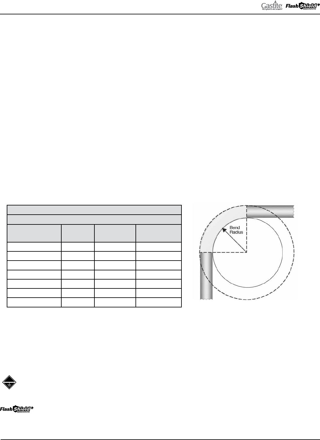
GASTITE DIVISION, TITEFLEX CORPORATION / 1116 Vaughn Parkway / Portland, TN 37148
800.662.0208 / www.gastite.com / [email protected]
47
SECTION 4: INSTALLATION PRACTICES / JANUARY 2020
SECTION 4.0 INSTALLATION PRACTICES
4.1 GENERAL PROVISIONS
a) Precautions must be taken to ensure any exposed Gastite/FlashShield
+
CSST is not damaged or abused during building
construction. All tubing, fittings and hardware should be stored in a clean, dry location prior to installation.
b) Open ends of the tubing are to be temporarily plugged or taped closed prior to installation to prevent entrance of dirt,
dust or other debris.
c) e protective plastic jacketing should be kept in place as much as possible to protect the tubing.
d) CSST and the system components including brass fittings and valves can be corroded by various chemical substances
which may be present on a job site or within a structure. Contact with these chemicals must be avoided. Any contact
should be immediately rinsed away.
e) Protect tubing from contact with sharp objects. When installing in, through, or around sharp metal structuring (i.e.
metal studs, sheet metal, I-beams, and fireplace enclosures) non-metallic grommets or tubing should be used to prevent
any direct contact which could subject tubing to damage.
f) Avoid stressing the tubing or fittings with tight bends, kinks, twists, stretching or repetitive bending. Refer to Table 4-1
below for the recommended minimum bend radius for Gastite/FlashShield
+
CSST (Fig. 4-1).
TABLE 4-1
BEND RADIUS
GASTITE
®
/
FLASHSHIELD
+
®
SIZE
EHD
ABSOLUTE MIN.
BEND RADIUS
SUGGESTED BEND
RADIUS
3/8" 13 3/4" 3.0"
1/2" 19 3/4" 3.0"
3/4" 23 1.0" 3.0"
1" 31 3.0" 5.0"
1-1/4" 37 3.0" 5.0"
1-1/2" 48 3.0" 5.0"
2" 60 4.0" 6.0"
g) Supporting Gastite/FlashShield
+
CSST — Tubing shall be supported in a workmanlike manner with pipe straps, bands
or hangers suitable for the size and weight of the tubing, at intervals not to exceed those shown in Table 4-3. A proper
support is one which is designed as a pipe hanger, does not damage the tubing during installation, and provides full
support. “J” Hooks may not be used as they may damage the Gastite/FlashShield
+
CSST. Zip ties/cable ties are not
to be used as a primary support but may be used to organize or bundle Gastite®/FlashShield
+
CSST. See Table 4-5 for
supporting Gastite/FlashShield
+
CSST in a rooftop application.
Direct contact between Gastite yellow CSST and continuous metallic systems is prohibited. When supporting
Gastite CSST tubing runs, the use of other conductive metallic systems such as metallic appliance vents, metallic
ducting and piping, and insulated or jacketed electrical wiring and cables should be avoided.
When supporting FlashShield
+
tubing runs, contact with other continuous metallic systems is acceptable.
h) Gastite/FlashShield
+
CSST must be rigidly terminated with a FS-Series or XR3 fitting. is can be achieved by
terminating with a rigidly mounted fitting or by terminating with a fitting threaded onto a rigid gas-piping component.
Fig. 4-1

GASTITE DIVISION, TITEFLEX CORPORATION / 1116 Vaughn Parkway / Portland, TN 37148
800.662.0208 / www.gastite.com / [email protected]
48
SECTION 4: INSTALLATION PRACTICES / JANUARY 2020
4.2 FIELD FITTING ASSEMBLY PROCEDURE
4.2.1 XR3 FITTING REV.2 TO FLASHSHIELD
+
CSST OR GASTITE YELLOW CSST
WITH JACKET STRIPPING TOOL
STEP 1 CUT-TO-LENGTH (FIG. 4-2)
Cut tubing to desired length using tubing cutter. Cut should be centered in a
corrugation valley. Use light roller pressure with extra rotations in one direction to
leave tubing round and free of burrs on cut.
To ensure a quality flare, all cuts should be made on a straight section of tubing.
Note: Tube ends are sharp use caution when handling.
STEP 2 CUT & STRIP JACKET LAYERS (FIG. 4-3, FIG. 4-4, FIG. 4-5)
Place cut-end of FlashShield
+
tubing into appropriate sized end of the stripping tool
up to the tube stop.
Close the stripping tool around tubing. Begin rotating the tool back and forth on the
CSST (3 – 5, 200º twists) while applying pressure until the blades cut through all
jacket layers.
Strip: To remove jacket section, release pressure and grasp the tool from the end. Pull
tool straight away from tubing while allowing the tool to open slightly so that the
blades can clear the peaks of the corrugations. Remove and discard the stripped jacket
layer(s) from the tool.
STEP 3 INSTALL NUT AND BUSHINGS (FIG. 4-6)
read fitting body (NPT thread) into valve or appliance connection. Slide nut onto
CSST and back a few inches. Separate bushings and position on tubing as shown, lo-
cating large bump into the valley of the first corrugation leaving one corrugation-peak
exposed between the end of the bushing and tubing.
Fig. 4-2
Fig. 4-3
Fig. 4-4
Fig. 4-5
Fig. 4-6
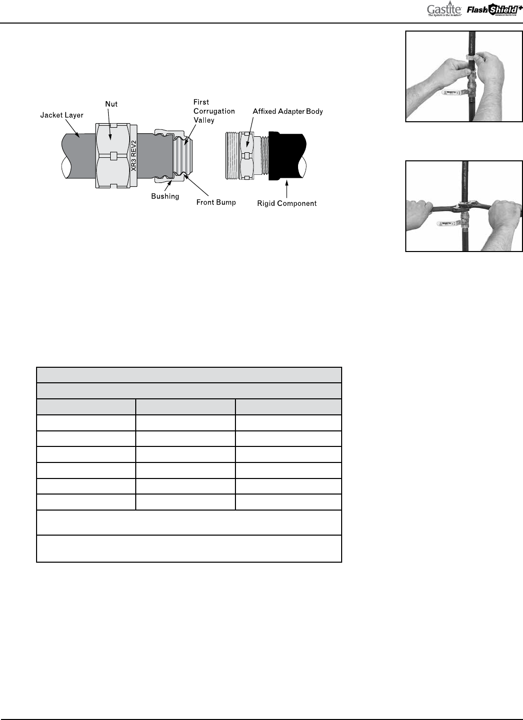
GASTITE DIVISION, TITEFLEX CORPORATION / 1116 Vaughn Parkway / Portland, TN 37148
800.662.0208 / www.gastite.com / [email protected]
49
SECTION 4: INSTALLATION PRACTICES / JANUARY 2020
STEP 4 POSITION BUSHINGS (FIG. 4-7)
Insert bushings into fitting body. A small amount of resistance indicates the
bushings are being compressed to further capture the jacket.
Note: Pipe dope or sealant is not to be used inside the fitting.
STEP 5 WRENCH FITTING (FIG. 4-8)
Slide nut over bushings and thread onto fitting body. Some resistance will be
experienced as the nut begins to compress the tubing and create the double-wall
flare. Continue to wrench the nut until the resistance increases greatly and the
double-wall flare is tightly seated.
Note: Rotate the nut only during the tightening process. Do not rotate the fitting body.
Note: e use of XR3 series fittings in combination with Gastite yellow tubing is an acceptable practice.
TABLE 4-2
RECOMMENDED TORQUE VALUES
SIZE EHD *TORQUE
1/2" 19 35 ft-lbs
3/4" 23 45 ft-lbs
1" 31 65 ft-lbs
1-1/4" 37 95 ft-lbs
1-1/2" 48 120 ft-lbs
2" 60 150 ft-lbs
Fitting is factory lubricated to reduce field torque requirements.
Lubrication must be chloride free.
* Minimum torque values supplied for lab testing reference only. Field installation
requirements: system must pass pressure/leak test (See Section 6).
Fig. 4-7
Fig. 4-8
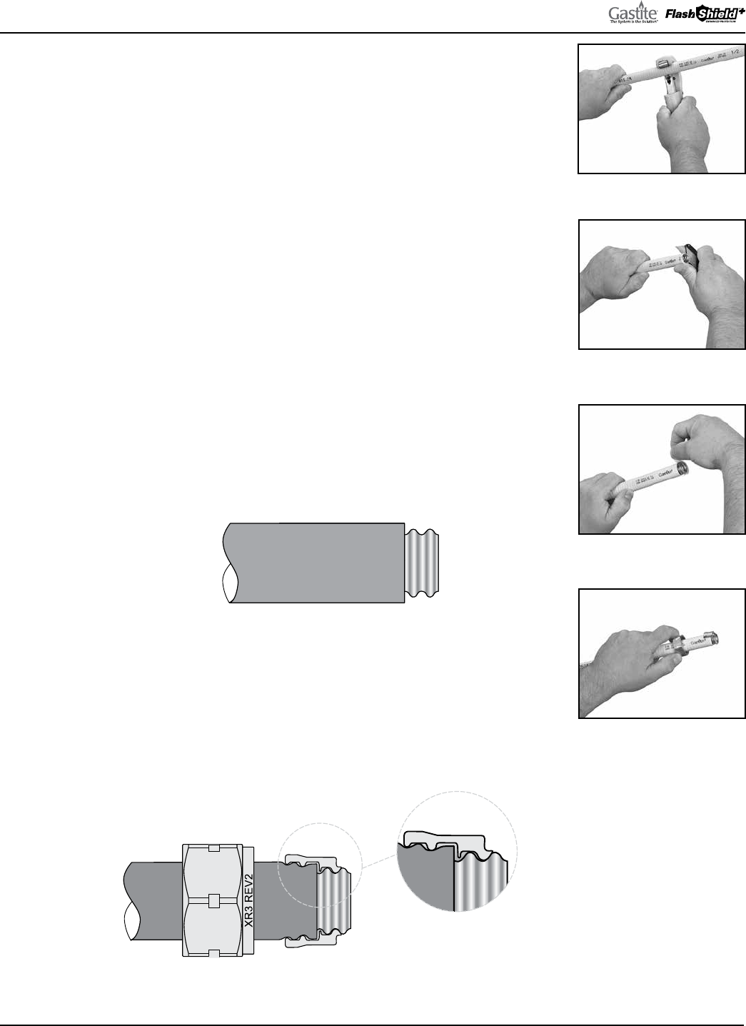
GASTITE DIVISION, TITEFLEX CORPORATION / 1116 Vaughn Parkway / Portland, TN 37148
800.662.0208 / www.gastite.com / [email protected]
50
SECTION 4: INSTALLATION PRACTICES / JANUARY 2020
4.2 FIELD FITTING ASSEMBLY PROCEDURES
4.2.2 XR3 FITTING REV.2 TO FLASHSHIELD+™ CSST OR GASTITE YELLOW CSST
(WITH UTILITY KNIFE)
STEP 1 CUT-TO-LENGTH (FIG. 4-9)
Cut tubing to desired length using tubing cutter. Cut should be centered in a
corrugation valley. Use light roller pressure with extra rotations in one
direction to leave tubing round and free of burrs on cut.
To ensure a quality flare, all cuts should be made on a straight section of tubing.
Note: Tubing ends are sharp, use care when handling.
STEP 2 STRIP JACKET (FIG. 4-10, FIG. 4-11)
Using a utility knife, cut jacket back to the second valley from tubing end.
Do not cut the jacket in such a way that the steel tubing end is scored.
(is could affect seating).
Remove the short section of jacket which will expose one full corrugation-
valley of the tubing.
Optionally, use side-1 of FlashShield
+
stripping tool for jacket strip.
STEP 3 INSTALL NUT AND BUSHINGS (FIG. 4-12)
read fitting body (NPT thread) into valve or appliance connection.
Slide nut onto tubing and back a few inches.
Separate bushings and position on tubing as shown, locating large bump
into the valley of the first corrugation leaving one corrugation-peak exposed
between the end of the bushing and tubing.
Fig. 4-9
Fig. 4-10
Fig. 4-11
Fig. 4-12
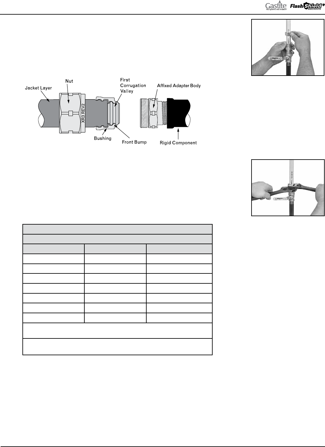
GASTITE DIVISION, TITEFLEX CORPORATION / 1116 Vaughn Parkway / Portland, TN 37148
800.662.0208 / www.gastite.com / [email protected]
51
SECTION 4: INSTALLATION PRACTICES / JANUARY 2020
STEP 4 POSITION BUSHINGS (FIG. 4-13)
Insert bushings into fitting body. A small amount of resistance indicates the
bushings are being compressed to further capture the jacket.
Note: Pipe dope or sealant is not to be used inside the fitting.
STEP 5 WRENCH FITTING (FIG. 4-14)
Slide nut over bushings and thread onto fitting body. Some resistance will be
experienced as the nut begins to compress the tubing and create the double-wall
flare. Continue to wrench the nut until the resistance increases greatly and the
double-wall flare is tightly seated.
Note: Rotate the nut only during the tightening process. Do not rotate the fitting body.
TABLE 4-2
RECOMMENDED TORQUE VALUES
SIZE EHD *TORQUE
3/8" 13 25 ft-lbs
1/2" 19 35 ft-lbs
3/4" 23 45 ft-lbs
1" 31 65 ft-lbs
1-1/4" 37 95 ft-lbs
1-1/2" 48 120 ft-lbs
2" 60 150 ft-lbs
Fitting is factory lubricated to reduce field torque requirements.
Lubrication must be chloride free.
* Minimum torque values supplied for lab testing reference only. Field installation
requirements: system must pass pressure/leak test (See Section 6).
Fig. 4-13
Fig. 4-14
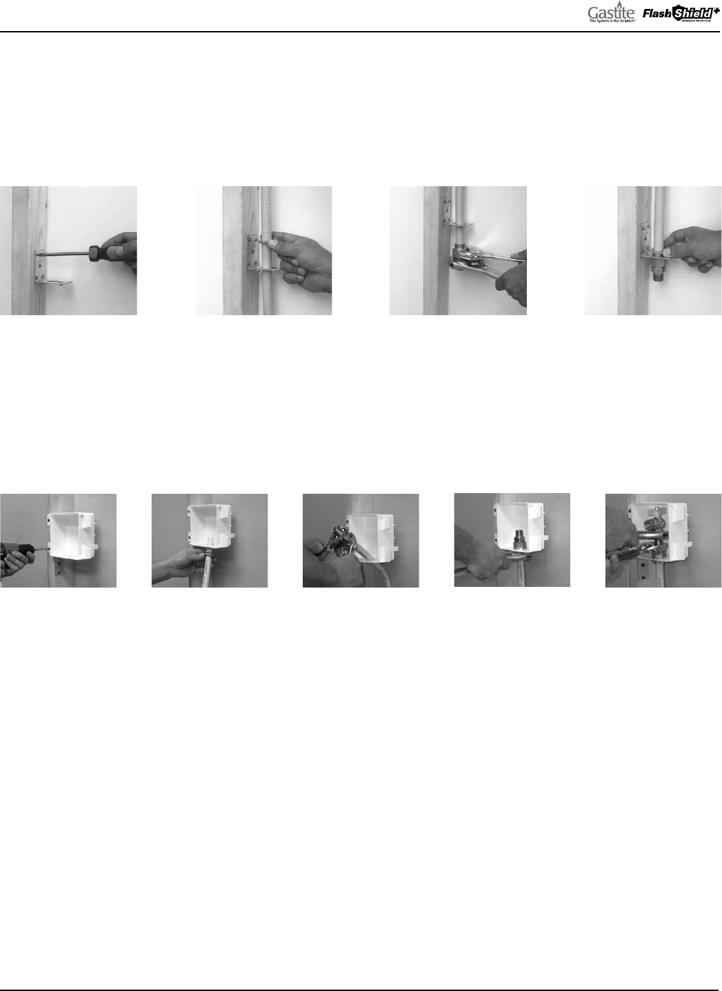
GASTITE DIVISION, TITEFLEX CORPORATION / 1116 Vaughn Parkway / Portland, TN 37148
800.662.0208 / www.gastite.com / [email protected]
52
SECTION 4: INSTALLATION PRACTICES / JANUARY 2020
4.2.4 OTHER ACCESSORY INSTALLATION
TERM BRACKET FITTING (FIG. 4-23 THROUGH FIG. 4-26)
1) Attach Bracket to stud or mounting surface.
2) Slide Jam-Nut over tubing and route tubing through Bracket.
3) Attach XR3 fitting to tubing.
4) Slide the XR3 fitting back onto Bracket and thread Jam-Nut.
XR3 OUTLET BOX (FIG. 4-27 THROUGH FIG. 4-31)
1) Mount Box and Bracket to stud or mounting surface.
2) Slide Jam-Nut over tubing and route tubing through Bracket and Box.
3) Attach Fitting to tubing.
4) Secure Jam-Nut to Fitting.
5) Attach Ball-Valve.
Note: Strike Protection (Floppy) not shown for clarity.
Step 1: Fig. 4-23
Step 1: Fig. 4-27 Step 2: Fig. 4-28 Step 3: Fig. 4-29 Step 4: Fig. 4-30 Step 5: Fig. 4-31
Step 2: Fig. 4-24 Step 3: Fig. 4-25 Step 4: Fig. 4-26
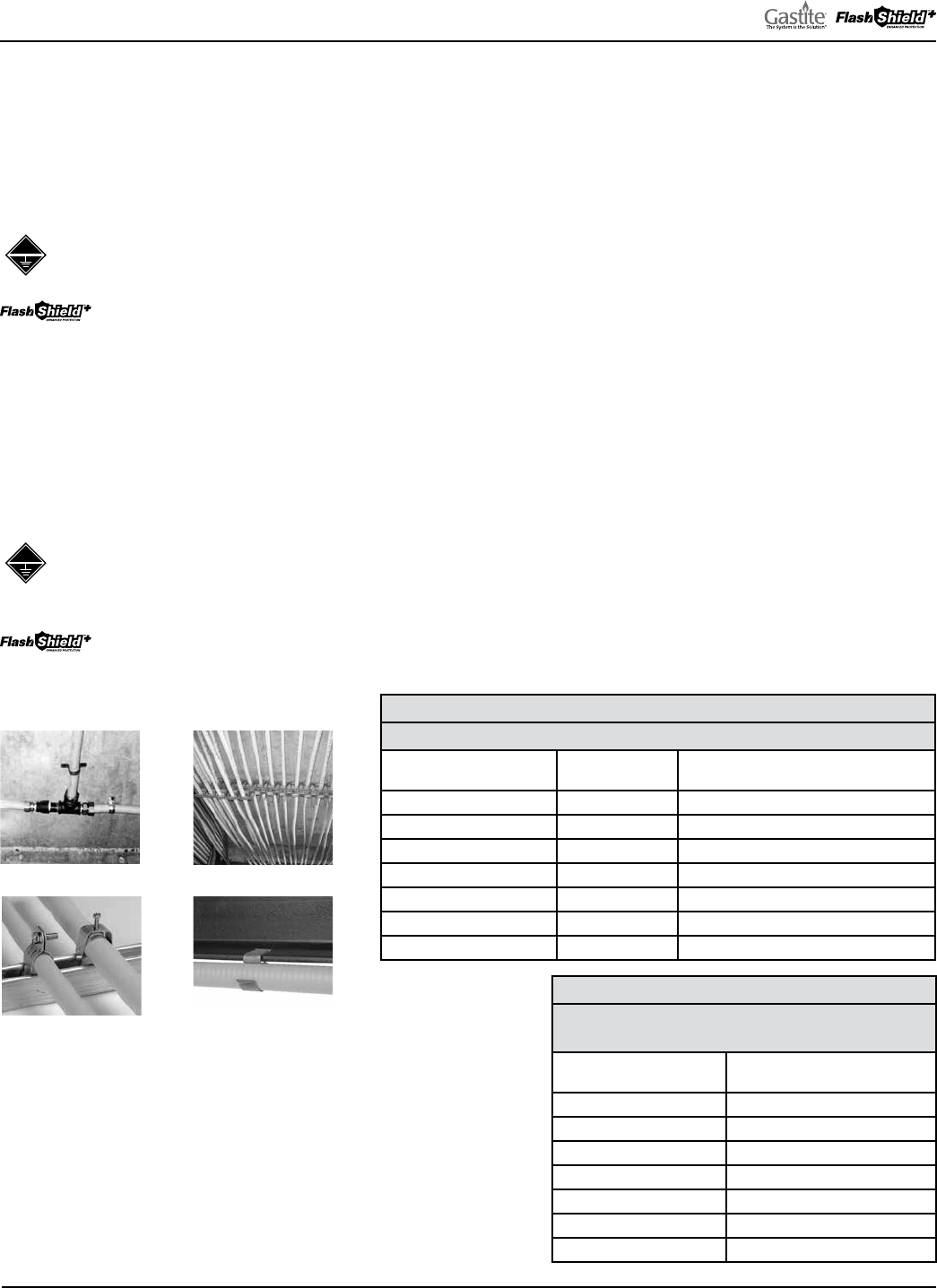
GASTITE DIVISION, TITEFLEX CORPORATION / 1116 Vaughn Parkway / Portland, TN 37148
800.662.0208 / www.gastite.com / [email protected]
53
SECTION 4: INSTALLATION PRACTICES / JANUARY 2020
4.3 ROUTING
4.3.1 VERTICAL RUNS
Tubing runs should be relatively plumb and free to move within the wall cavity without any physical support between
the floors. For support requirements refer to Section 4.1.f. Where any run is greater than two stories or 20-ft, additional
support (appropriate to the weight of the tubing) must be provided at the point of penetration through the floor.
Direct contact between Gastite yellow CSST and continuous metallic systems is prohibited. When installing vertical runs,
maintain as much isolation/separation as reasonably possible from other continuous metallic systems in the building.
ere is no requirement to maintain separation from other electrically conductive systems when routing
FlashShield
+
4.3.2 HORIZONTAL RUNS
Tubing routed on top of ceiling joists and other structural members which comply with the horizontal support spacing
requirements will be considered sufficiently supported. See Figures 4-32, 4-33, 4-34 and 4-35 for examples of acceptable
support configurations when routing Gastite/FlashShield
+
. Gastite/FlashShield
+
may be routed beneath, through and
alongside floor and ceiling joists. Due consideration must be given to future construction possibilities. Horizontal runs in
concealed areas must conform to Section 4.4 Protection.
Direct contact between Gastite yellow CSST and continuous metallic systems is prohibited. When installing
horizontal runs, maintain as much isolation/separation as reasonably possible from other continuous metallic
systems in the building.
ere is no requirement to maintain separation from other continuous metallic systems when routing
FlashShield
+
TABLE 4-3
SUPPORT SPACING (NON-ROOFTOP, NON-WALL CAVITY)
GASTITE/
FLASHSHIELD+ SIZE
EHD VERTICAL OR HORIZONTAL
3/8" 13 4 Feet
1/2" 19 6 Feet
3/4" 23 8 Feet (USA) 6 Feet (Canada)
1" 31 8 Feet (USA) 6 Feet (Canada)
1-1/4" 37 8 Feet (USA) 6 Feet (Canada)
1-1/2" 48 8 Feet (USA) 6 Feet (Canada)
2" 60 8 Feet (USA) 6 Feet (Canada)
4.3.3 INSTALLATION CLEARANCE HOLES
Clearance holes for routing Gastite/FlashShield
+
CSST are to
be approximately 1/2 inch greater than the O.D. of the Gastite/
FlashShield
+
CSST. Drilling of any structural member must be in
conformance with the local building code. Refer to Table 4-4 for the
recommended drill hole sizing.
TABLE 4-4
GASTITE/FLASHSHIELD+
CLEARANCE HOLES
GASTITE/
FLASHSHIELD+ SIZE
DRILL HOLE SIZE
3/8" 1"
1/2" 1-1/4"
3/4" 1-1/2"
1" 1-3/4"
1-1/4" 2"
1-1/2" 2-1/4"
2" 3"
Fig. 4-32
Fig. 4-34
Fig. 4-33
Fig. 4-35
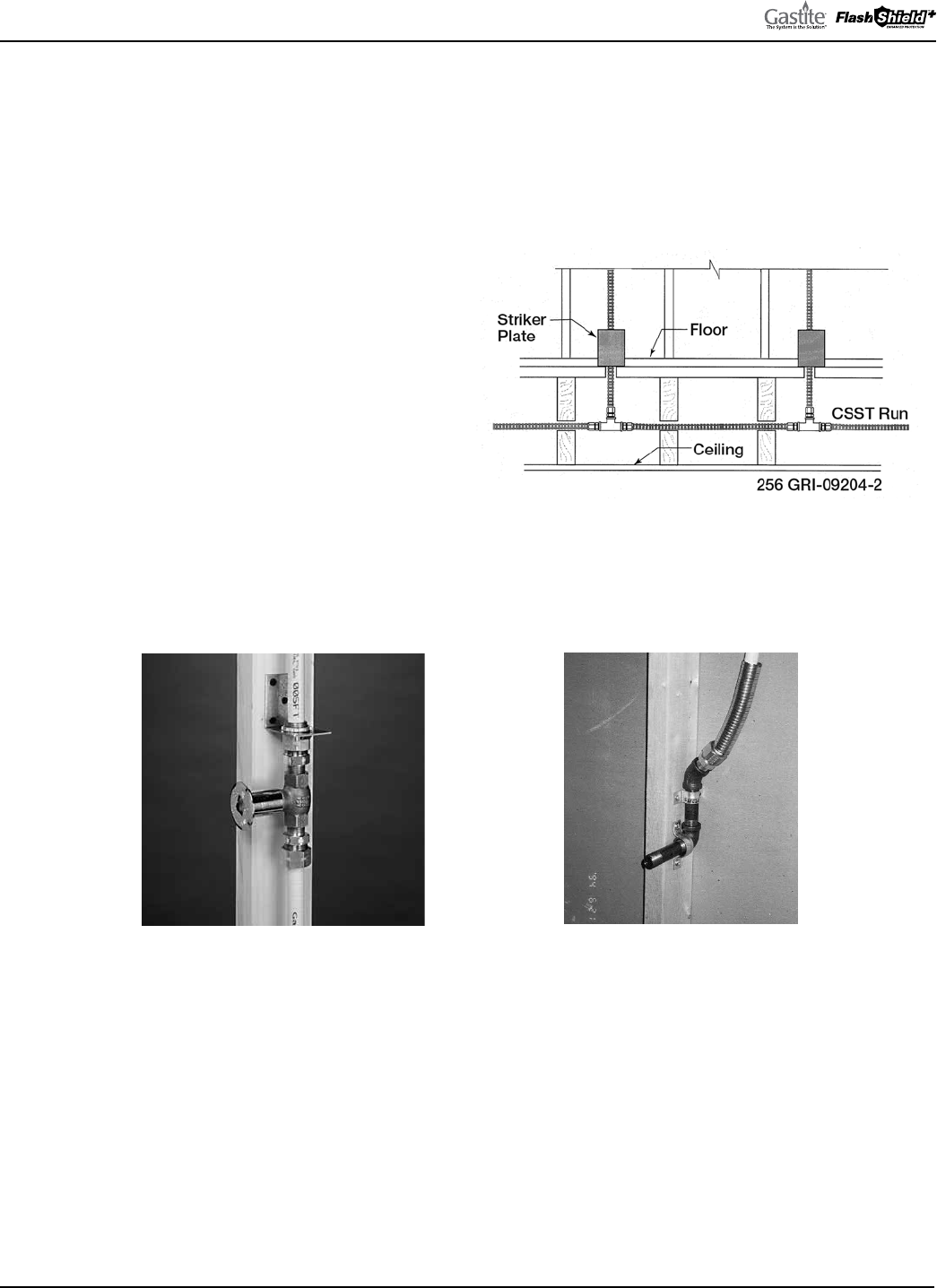
GASTITE DIVISION, TITEFLEX CORPORATION / 1116 Vaughn Parkway / Portland, TN 37148
800.662.0208 / www.gastite.com / [email protected]
54
SECTION 4: INSTALLATION PRACTICES / JANUARY 2020
4.3.4 CONCEALED FITTINGS
e Gastite/FlashShield
+
Mechanical Fittings have been tested and listed per the requirements of ANSI LC1/CSA 6.26 for
concealed use. e fitting may be used for concealed attachment including, but not limited to: appliance valves, branch
runs using tee fittings, length splices and stub-outs manufactured from approved fuel gas piping materials.
ese guidelines cannot address all applications of concealed fittings, but instead, provide typical instructions to
demonstrate the principles that apply to fittings listed for installation in concealed locations. (Reference National Fuel Gas
Code, NFPA 54, Concealed Piping in Buildings).
a) New Installations (Fig. 4-36) – When multiple gas
outlets are supplied from a single run of Gastite/
FlashShield
+
CSST, each downstream outlet branch
can be connected to the main run using a tee-type
fitting which can be located in a concealed location.
b) Fireplace key valves (Fig. 4-37) – Gastite/FlashShield
+
CSST connections to fireplace key valves can be
located in a concealed location when accessibility
is not readily provided.
Note: Strike protection (floppy) not shown, for clarity.
c) Stub-outs (Fig. 4-38) – Gastite/FlashShield
+
CSST
connections to stub-outs fabricated from approved
fuel gas piping materials.
d) Exclusion – Manifold stations for dual pressure systems which include the multi-port manifold, shut-off valve and
pressure regulator shall not be installed in concealed locations regardless of the qualifications of the tubing.
4.3.5 MODIFICATIONS TO EXISTING SYSTEMS
a) New Ceilings in Unfinished Rooms/Basements – Gastite/FlashShield
+
CSST fittings originally installed in accessible
ceiling locations can be concealed in the event a ceiling is installed at a later date.
b) Extensions to Existing Tubing Runs – Concealed tubing can be modified to permit an extension to another appliance
location provided there is sufficient capacity to supply both appliances at the same time. If an accessible location for the
modification is not available, the existing tubing run can be modified with a tee fitting that will result in a concealed
fitting behind the wallboard.
c) When modifications lead to concealed tubing, strike protection may be required. Refer to Section 4.4.
Fig. 4-37
Note: Strike Protection (Floppy) not shown for
clarity.
Fig. 4-38
Fig. 4-36

GASTITE DIVISION, TITEFLEX CORPORATION / 1116 Vaughn Parkway / Portland, TN 37148
800.662.0208 / www.gastite.com / [email protected]
55
SECTION 4: INSTALLATION PRACTICES / JANUARY 2020
4.3.6 OUTDOOR
Gastite/FlashShield
+
Flexible Gas Tubing has passed all requirements of ANSI LC1/CSA 6.26, which include testing for
suitability for exposure of CSST piping systems to outdoor environments.
a) Outdoors – When installed outdoors, the external jacketing shall remain intact as much as practical for the given
installation. Any portions of the exposed stainless steel tubing shall be wrapped with tape or sleeved to prevent threats by
corrosive chemicals, especially chlorides. Self-bonding silicone tape is recommended here for durability.
b) Along side a structure – When installed along the outside of a structure (between the ground and a height of 6 ft) in an
exposed condition, the Gastite/FlashShield
+
CSST shall be protected from mechanical damage inside a conduit or chase.
A conduit or chase is not required if the tubing is installed in a location that will not subject the Gastite/FlashShield
+
CSST to mechanical damage.
4.3.7 FIRE RATED CONSTRUCTION
e Gastite/FlashShield
+
jacket is ASTM E84 and CAN/ULC-S102.2 25/50 compliant for the flame smoke spread and
density index. ese values meet most typical requirements for building construction. erefore, the jacket should remain
intact when passing through typical building constructions such as plenums, floor and ceiling joists, rim joists, walls or
other fire rated resistance construction limited to materials of ASTM E84 or CAN/ULC-S102.2 ratings of 25 flame and
50 smoke, or lower.
A plenum is defined as an enclosed portion of the building structure that is designed to allow air movement, and thereby
serve as part of an air distribution system. (See definition of Plenum, Section 8.0.) No gas tubing may be run within
ductwork.
For tubing passing through a UL classified fire rated construction, UL Classified Systems for “rough-Penetration
Firestop Systems (XHEZ)” may be found in UL Fire Resistance Volume 2. In instances that UL specifications for fire rated
construction conflict with the current Gastite® Design and Installation Guide, UL takes precedence.
4.3.8 ROUTING THROUGH MASONRY MATERIAL
“Masonry material” includes but is not limited to brick, concrete, mortar, and stucco. e term “through masonry
construction” refers to any enclosed/concealed construction spaces where CSST is routed in close proximity to masonry
but does not apply to exposed CSST mounted to a set masonry surface.
When it is necessary to install Gastite/FlashShield
+
through masonry materials the tubing shall be routed through a con-
duit that is 1/2" larger in diameter (to ease routing) than the OD of the CSST and appropriate for the application. e
sleeve must maintain a continuous watertight barrier between the masonry material and the CSST, up to or past the edge
of the masonry hole. Masonry encasement refers to any enclosed/concealed construction within “masonry material” that
produces distributed loads. For masonry encasement see Underground Installations (Section 4.9).
4.3.9 INSTALLATION WITHIN A CHIMNEY CHASE
Gastite yellow tubing shall not be installed within a chase and/or enclosure that includes a metallic appliance vent
and/or metallic chimney liner that protrudes through and/or past the roof.
FlashShield
+
CSST may be routed within a chimney chase.
4.3.10 CLEARANCE FROM THE UNDERSIDE OF A ROOF DECK
a) A minimum of 3 inches of separation should be maintained from the underside of a shingled roof deck to take into
account the potential of roof nail penetration due to future repair and/or replacement of the roof.
b) Gastite CSST shall not come in contact with reflective radiant barrier insulation that is attached to the underside
of a roof deck.
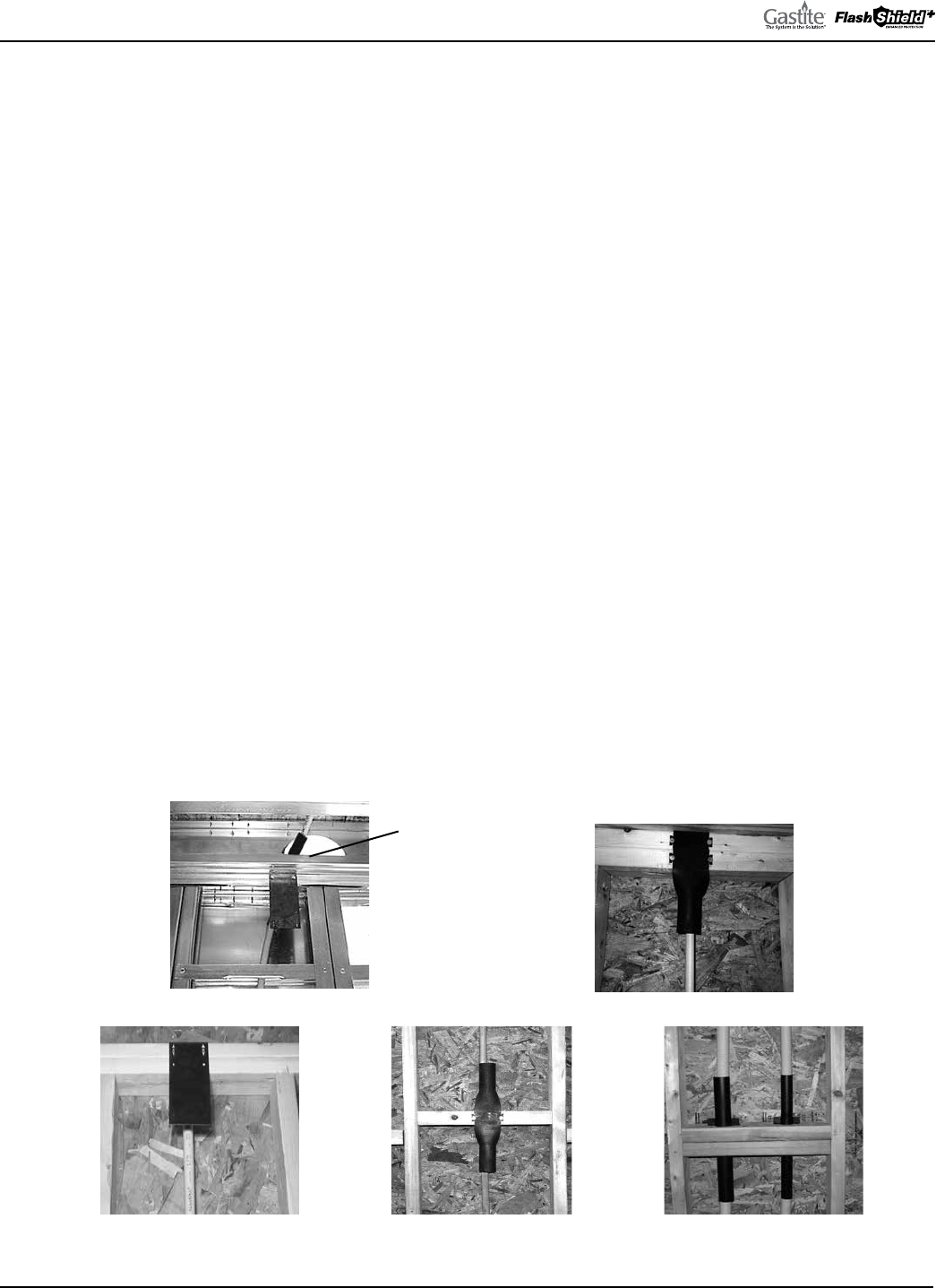
GASTITE DIVISION, TITEFLEX CORPORATION / 1116 Vaughn Parkway / Portland, TN 37148
800.662.0208 / www.gastite.com / [email protected]
56
SECTION 4: INSTALLATION PRACTICES / JANUARY 2020
4.4 STRIKE PROTECTION
Concealed Gastite/FlashShield
+
CSST should be routed in areas that will minimize the opportunity for physical damage
and/or installed in areas where the tubing will be free to move to avoid a potential puncture threat. e tube can be
considered free to move when there is at least the tube’s outside diameter of clearance on all sides of the tubing.
Gastite/FlashShield
+
CSST installed in locations subject to physical damage shall be adequately protected. e tubing shall
be protected at points of support and when passing through structural members such as studs, joists and plates. Where all
three of the following conditions exist, mechanical strike protection must be used.
1) Concealed – View is obstructed by walls, and structural members.
2) Constrained – Tubing is not free to move to avoid puncture threats.
3) Within 3 inches of a potential threat – Tubing is routed in locations which are within 3 inches of drills, screws, or nails.
4.4.1 STRIKE PLATES
For Gastite/FlashShield
+
CSST which meets all three of the conditions above, the required method for protecting concealed
tubing is hardened steel striker plates listed for use with corrugated stainless steel tubing systems. Striker plates are used at
all points of penetration through studs, joists, plates or similar structures (Figures 4-39, 4-40, 4-41, 4-42 and 4-43). Striker
plates other than those provided or specified by Gastite are strictly prohibited.
e extent of protection shall be defined as follows:
a) At concealed support points and points of penetration less than 2 inches from any edge of a stud, joist, plate, etc., a listed
striker plate is required at the area of support to provide coverage for 5 inches from the point of restraint in one or both
directions (Fig. 4-44).
Fig. 4-41 Fig. 4-42
Fig. 4-40
Fig. 4-43
Note: Steel Stud
Construction –
Knock teeth off striker
plate for steel stud
construction.
Fig. 4-39
NON-METALLIC
HOSE
PROTECTION
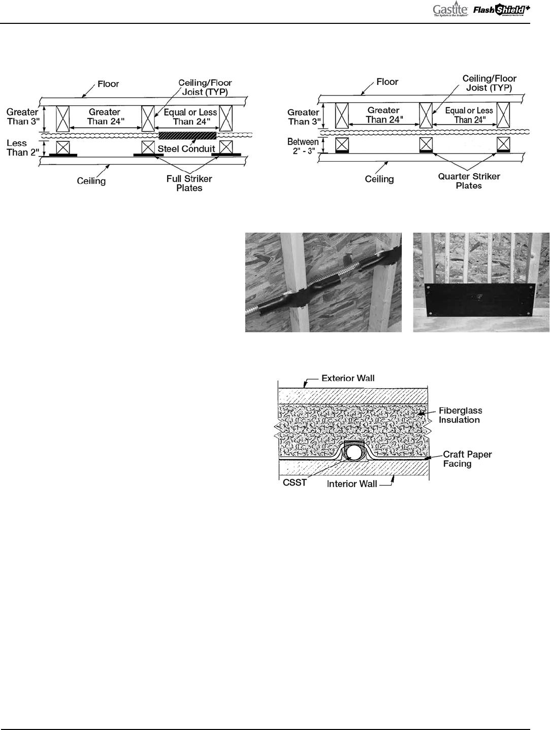
GASTITE DIVISION, TITEFLEX CORPORATION / 1116 Vaughn Parkway / Portland, TN 37148
800.662.0208 / www.gastite.com / [email protected]
57
SECTION 4: INSTALLATION PRACTICES / JANUARY 2020
b) At concealed support points and points of penetration 2 to 3 inches from any edge of a stud, joist plate, etc., listed 1/4
striker plates are required to provide protection throughout the area of penetration (Fig. 4-45).
c) When multiple runs are located between the same
two studs such as manifold runs or meter bank
runs, a 6" x 17" panel type striker plate may be used
as an alternate to individual striker plates for each
tubing run (Fig. 4-47).
d) When installed inside insulated exterior walls,
tubing shall be routed between the face of the
insulation and the interior wall surface (Fig. 4-48).
If rigid insulation is used, enough space must be
provided for movement of the tubing (see Section
4.4) or heavy wall conduit must run over the length of
the restrained area.
e) At points of penetration greater than 3 inches from
any edge of stud, joist, plate, etc., no protection is
required.
f) Tubing routed horizontally through structural members
shall be protected from puncture threats with the
appropriate shielding material (Figure 4-46 and 4-47).
At penetration points, listed plates of the appropriate
size shall be utilized Tubing between constraints that are less than 24 inches apart and meeting the criteria requiring full
striker plates, shall be additionally protected by Steel Conduit (Fig. 4-48).
g) Gastite/FlashShield
+
CSST greater than 1" nominal diameter installed within a concealed hollow wall cavity of 2"x4"
construction shall be protected along the entire concealed run length with Steel Conduit (see Section 4.4.2).
h) e width of installed striker plates shall be at least 1.5 times the outside diameter of the Gastite/FlashShield
+
CSST.
Fig. 4-44
Fig. 4-45
Fig. 4-46
Fig. 4-48
Fig. 4-47
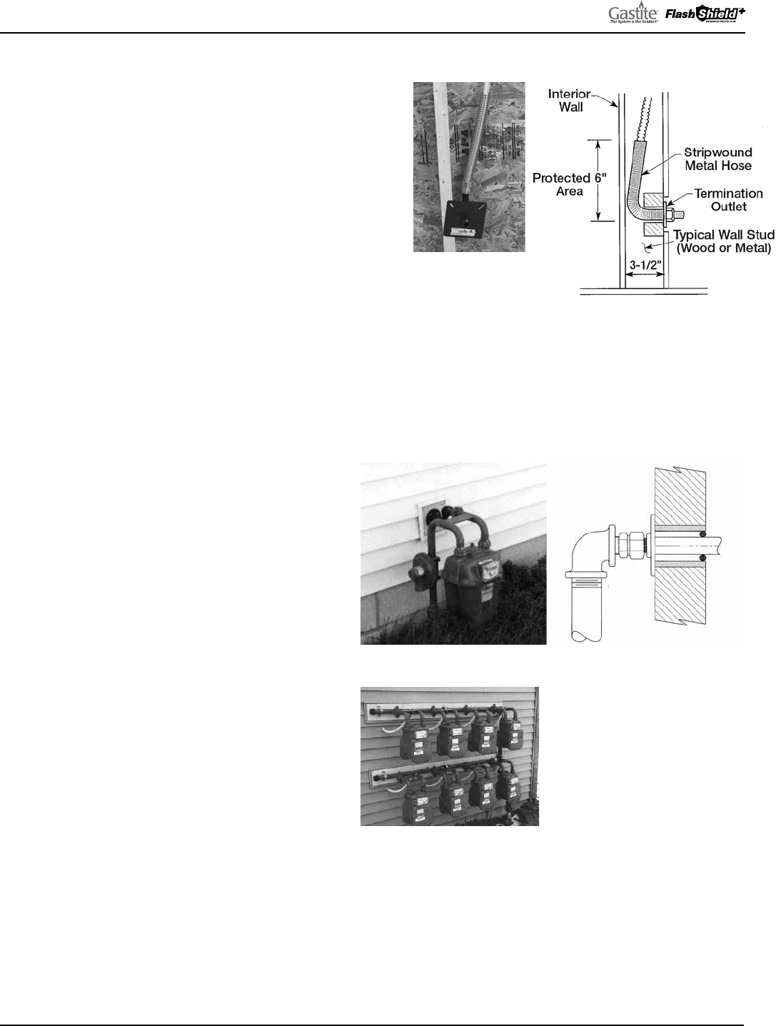
GASTITE DIVISION, TITEFLEX CORPORATION / 1116 Vaughn Parkway / Portland, TN 37148
800.662.0208 / www.gastite.com / [email protected]
58
SECTION 4: INSTALLATION PRACTICES / JANUARY 2020
4.4.2 STEEL CONDUIT
At termination points not covered by the ANSI standard,
floppy steel conduit (heavy wall) shall be installed as
additional protection (Fig. 4-49 and 4-50). Gastite/
FlashShield
+
requires a minimum of six inches of conduit
and supplies precut conduit in one foot lengths. Floppy Steel
conduit should not be used in place of hardened steel striker
plates when passing through structural members.
4.5 METER
e gas piping for the meter stub-out is usually subject to local
requirements such as size, location, and material type. It is always
important to confirm local code and utility requirements. Gastite/FlashShield
+
recommends the use of 1/2" CSST or greater as the minimum trunk line size. Size
3/8" should not be used for trunk lines. is will allow for the addition of future gas
appliances and minimize the opportunity for whistling.
a) Unsupported Meters – Meters that depend on
the service supply line and/or the house piping
for support shall not be directly connected to the
Gastite/FlashShield
+
CSST. As shown in the Figures
4-51 and 4-52, a rigid connection point is created
using a Gastite/FlashShield
+
termination fitting,
Gastite designed stub-out or rigid pipe components.
b) Self-Supported Meters – Meters that are
independently supported with a bracket can be
directly connected to the Gastite/FlashShield
+
CSST as shown in Figure 4-53. If practical, direct
Gastite/FlashShield
+
CSST connections shall
include a 3 to 6 inch loop of tubing (as shown)
to accommodate differential settling and meter
movement. No mechanical protection of the tubing
is required for outdoor meter connections; however,
ensure that the local utility supports this practice
as some utilities have regulations specifying meter
attachments.
c) Electrical bonding connections made at the gas meter
must comply with Section 4.10 of this guide.
Fig. 4-49
Fig. 4-50
Fig. 4-51 Fig. 4-52
Fig. 4-53
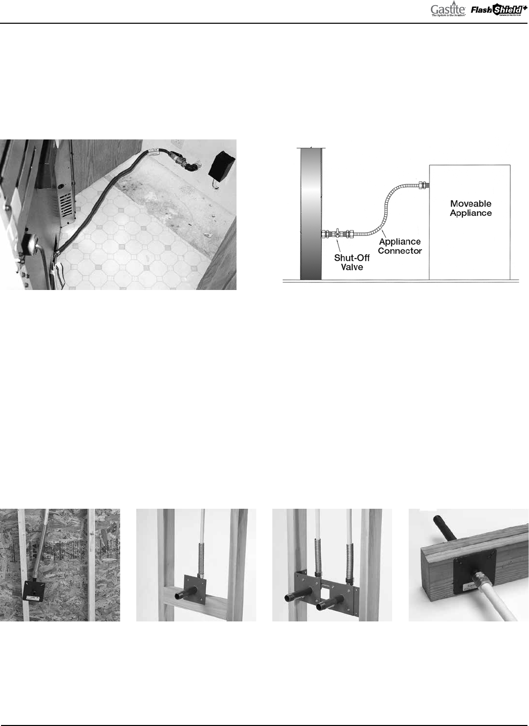
GASTITE DIVISION, TITEFLEX CORPORATION / 1116 Vaughn Parkway / Portland, TN 37148
800.662.0208 / www.gastite.com / [email protected]
59
SECTION 4: INSTALLATION PRACTICES / JANUARY 2020
4.6 APPLIANCE
4.6.1 MOVEABLE APPLIANCE
a) For use with movable appliances, Gastite/FlashShield
+
must be rigidly terminated before the appliance connection. is
fixed connection point allows for the attachment of flexible appliance connectors, drip legs (if required), and shut off
valves to moveable appliances such as dryers and ranges (Figures 4-54 and 4-55)
b) e Appliance Stub-Out is mounted to a stud face (Fig. 4-56) and provides a fixed point to which a Gastite/
FlashShield
+
mechanical fitting may be attached. e design of this stub-out ensures that the flexible tubing is routed
away from any points of constraint that may subject the tubing to potential puncture threats.
c) e Straight Stub provides a fixed point for the Gastite/FlashShield
+
mechanical fitting and a stable platform for service
meter connections. e Straight Stub may be mounted to the face of a stud (Fig. 4-57) or mounted to an optional
Stub Bracket with supplied self-drilling metal screws (Fig. 4-58). e optional bracket is designed to span typical stud
construction. e compact design of the straight stub allows for multiple stub-outs within the stud cavity.
e Straight Stub may also be used to pass through joist and wall constructions (Fig. 4-59). It is important to follow all
requirements for sleeving when passing through masonry construction.
Fig. 4-54 Fig. 4-55
Fig. 4-56 Fig. 4-57 Fig. 4-58 Fig. 4-59
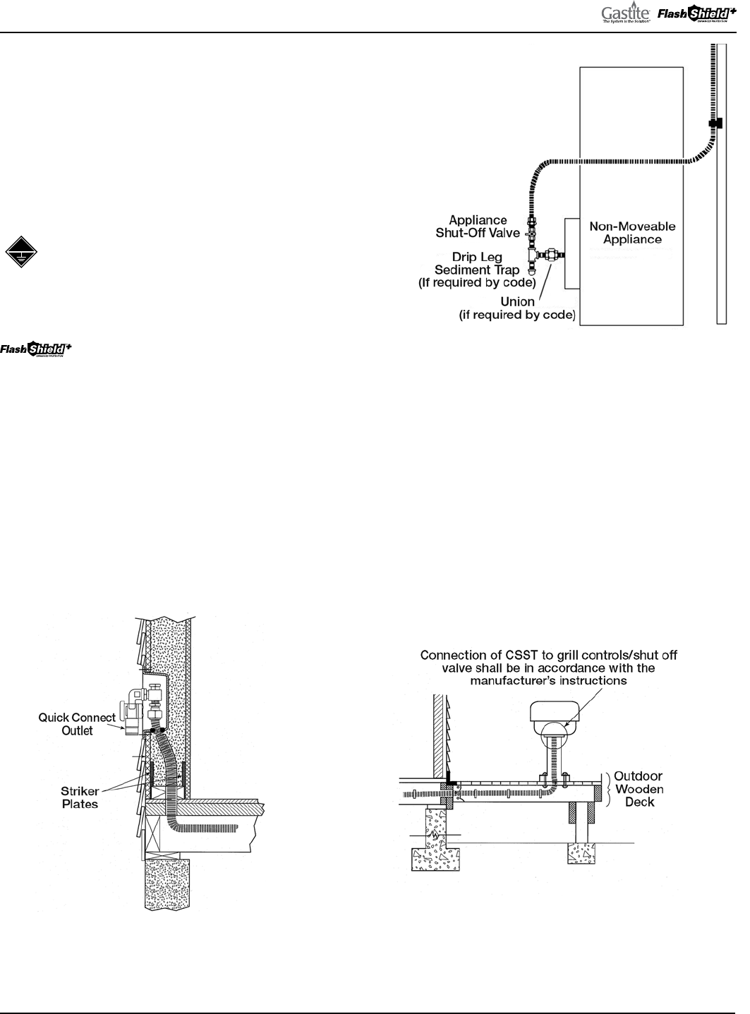
GASTITE DIVISION, TITEFLEX CORPORATION / 1116 Vaughn Parkway / Portland, TN 37148
800.662.0208 / www.gastite.com / [email protected]
60
SECTION 4: INSTALLATION PRACTICES / JANUARY 2020
4.6.2 DIRECT CONNECTION – NON-MOVEABLE APPLIANCES
Gastite/FlashShield
+
CSST may be connected directly to non-movable
appliances such as water heaters, furnaces, boilers and island cook-tops
(Figure 4-60) without the installation of a termination outlet or flexible
appliance connector. All local codes requiring drip legs and shut-off
valves must be observed. Drip legs and shut-off valves must be securely
mounted. Additionally, Gastite/FlashShield
+
shall not penetrate
metallic cabinet of appliance.
When appliances such as water heaters, furnaces or boilers
have metallic vents which extend beyond or protrude through
the roof physical contact between the Gastite CSST and the
appliance cabinet or vent is prohibited. Gastite recommends that all
continuous metallic systems be bonded and grounded.
Physical contact with appliance cabinets that have metallic
vents which extend beyond or protrude through the roof
is acceptable.
4.6.3 GAS CONVENIENCE OUTLET
a) Barbecue Grills – Movable grills shall be connected using an approved outdoor appliance connector which shall be attached
to the CSST system either at a termination fitting or a quick disconnect device as shown in the figure (Fig. 4-61).
b) Permanently mounted grills located on decks (Fig. 4-62) shall be connected to the CSST system as shown in the figure
and in accordance with the manufacturer’s instructions. e outdoor portion of the CSST run shall be supported against
the side of any of the inside deck joists.
Fig. 4-61 Fig. 4-62
NOTE: STRIKE PROTECTION
(FLOPPY) NOT SHOWN FOR CLARITY.
Fig. 4-60
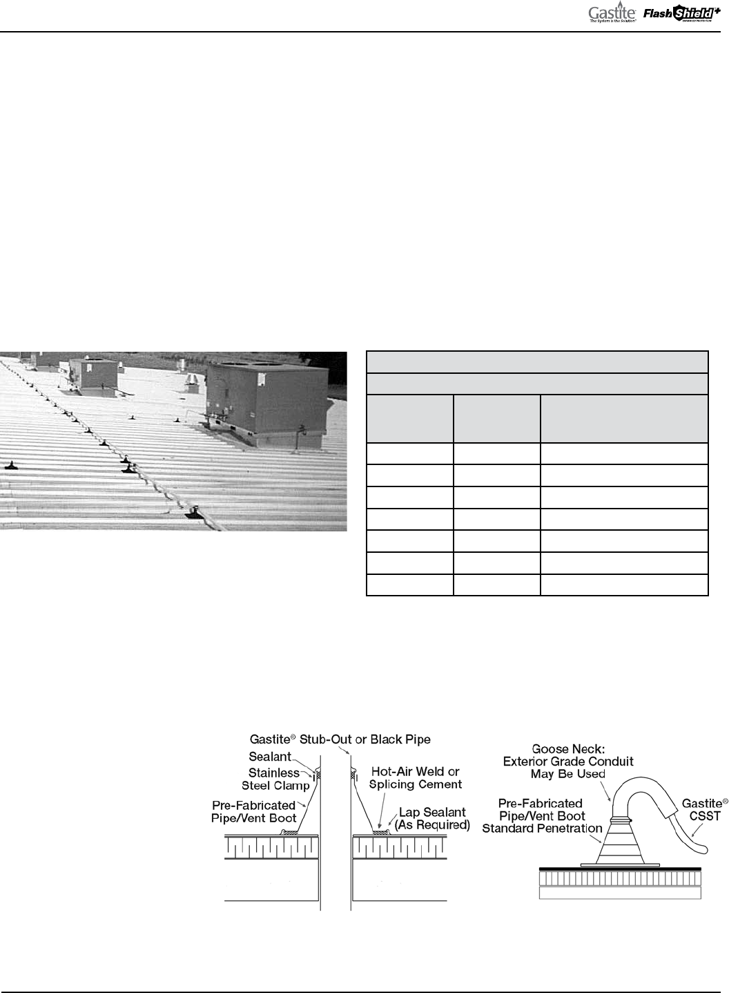
GASTITE DIVISION, TITEFLEX CORPORATION / 1116 Vaughn Parkway / Portland, TN 37148
800.662.0208 / www.gastite.com / [email protected]
61
SECTION 4: INSTALLATION PRACTICES / JANUARY 2020
4.6.4 SPECIAL APPLICATIONS
a) Roof Mounted Equipment (Fig. 4-63) – Gastite/FlashShield
+
Flexible Gas Piping can be used in an outdoor rooftop
application. When used in this application, the CSST is to be supported off the surface of the roofing material. is
support allows for adequate drainage on the roof, product protection from snow, and is commonly required by code.
When Gastite/FlashShield
+
Flexible Gas Piping is installed in an outdoor rooftop application the following
requirements must be met:
1. Support materials will be selected to provide an adequate anchoring point that addresses the lightweight flexible
nature of Gastite/FlashShield
+
. is can be accomplished through either the weight of the support or adhering the
support to the roof materials. e support materials must also be selected to be non-damaging to the roofing material.
(Check with roof material manufacturer for approved adhering methods and non-damaging materials/installations.)
2. It is also important to select the appropriate metal pipe clamps or straps to firmly affix the tubing to the support.
3. e supports shall lift the tubing at least 3" from the surface of the roof, higher as required by code or local conditions.
(Check with local code officials to determine height requirements as defined by the local code or conditions).
4. Support spacing will follow the recommendations as outlined in Table 4-5 below.
TABLE 4-5
ROOF TOP SUPPORTING SPACE
GASTITE/
FLASHSHIELD+
SIZE
EHD MAX SUPPORT SPACING
3/8" 13 6 Feet
1/2" 19 6 Feet
3/4" 23 6 Feet
1" 31 8 Feet
1-1/4" 37 8 Feet
1-1/2" 48 8 Feet
2" 60 8 Feet
Gastite/FlashShield
+
shall penetrate roofing in the manner and using the materials as defined by the roofing manufacturer
in order to maintain the manufacturer’s warranty (Figures 4-64 and 4-65). When passing through the deck Gastite/
FlashShield
+
must be properly terminated or pass through an appropriate fixed conduit (Figures 4-66 and 4-67). NOTE:
As roofing manufacturers generally have proprietary penetration systems and require trained installers, it is extremely
important to obtain approval and instructions from the roofing manufacturer prior to performing any work. Failure to do
so can result in voiding the roofing warranty.
Lengths of Gastite/FlashShield
+
CSST which run vertically up
the side of the building shall be
protected in accordance with the
General Provisions section of
these guidelines, Section 4.3.6.
Fig. 4-63
Fig. 4-64 Fig. 4-65

GASTITE DIVISION, TITEFLEX CORPORATION / 1116 Vaughn Parkway / Portland, TN 37148
800.662.0208 / www.gastite.com / [email protected]
62
SECTION 4: INSTALLATION PRACTICES / JANUARY 2020
Fig. 4-66
Fig. 4-67
a) Pad Mounted Equipment (Fig. 4-68) – Moveable gas appliances on concrete pads or blocks, such as heat pumps, air
conditioners, pool heaters and NGV refueling systems, shall be connected to the Gastite/FlashShield
+
CSST system
at a termination fitting using either rigid pipe or an approved outdoor appliance connector.
b) Gas Packs and Other Non-Moveable Equipment (Fig. 4-69) – Can be connected to the Gastite/FlashShield
+
CSST
system either through a terminating fitting and rigid pipe or directly with Gastite/FlashShield
+
CSST connected to the
appliance shut-off valve.
Fig. 4-68 Fig. 4-69
c) Gas Lamps – Permanently mounted lights located on
decks shall be connected to the Gastite/FlashShield
+
CSST system in the same fashion as permanently
mounted grills as shown in the figure and in accordance
with the manufacturers instructions.
d) Yard Mounted Lights – Shall be connected to the
Gastite/FlashShield
+
CSST system as shown in Figure
4-70. All Gastite/FlashShield
+
CSST installed below
grade shall be installed in accordance with Section 4.9.
Fig. 4-70
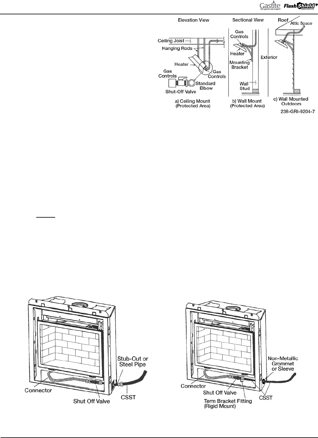
GASTITE DIVISION, TITEFLEX CORPORATION / 1116 Vaughn Parkway / Portland, TN 37148
800.662.0208 / www.gastite.com / [email protected]
63
SECTION 4: INSTALLATION PRACTICES / JANUARY 2020
e) Infrared heaters (Fig. 4-71) that are solidly
mounted to ceilings and walls of structures
may be connected to the Gastite/FlashShield
+
CSST system as shown in the figures below
and in accordance with the manufacturers
instructions. High Density infrared heaters
generally fall into this category. Gastite/
FlashShield
+
CSST should be mounted to
a fixed point and not on the end involved
with the typical expansion and contraction
associated with these heaters.
Infrared heaters that are mounted to allow
movement of the heater must use an appropriate
appliance/flex connector between the heater and the properly terminated Gastite/FlashShield
+.
Low Density heaters,
tube heaters and heaters hung from chains fall into this category.
Heaters and installations must comply with ANSI Z83.6, “Standard for gas fired infrared heaters.”
f) Gastite/FlashShield
+
CSST shall not be directly routed into the metallic enclosure of a gas fireplace utilizing a metallic vent
that penetrates a roofline. e CSST connection shall be made outside of the metallic gas enclosure to a section of rigid
metallic pipe, stub-out, or termination fitting. See Fig. 4-72.
g) Where it is necessary to install Gastite/FlashShield
+
CSST through the sheet metal enclosure of a gas fireplace utilizing a
vent which does not penetrate a roofline, the tubing shall be routed and supported to permanently prevent physical contact
with any portion of the metallic enclosure. To avoid contact with the enclosure at the point of penetration, a non-metallic
grommet or non-metallic tube/sleeve shall be used. See Fig. 4-73. Otherwise, a steel stub-out or steel pipe components
must be used with the CSST terminated outside the enclosure.
Gastite/FlashShield
+
CSST and the brass fittings should not be used inside the firebox for log lighters/gas wands or in
any firebox where wood logs will be burned due to the potential for physical harm to the tubing.
Fig. 4-71
Fig. 4-72 Roof-vented Fireplace Fig. 4-73 Wall-vented Fireplace
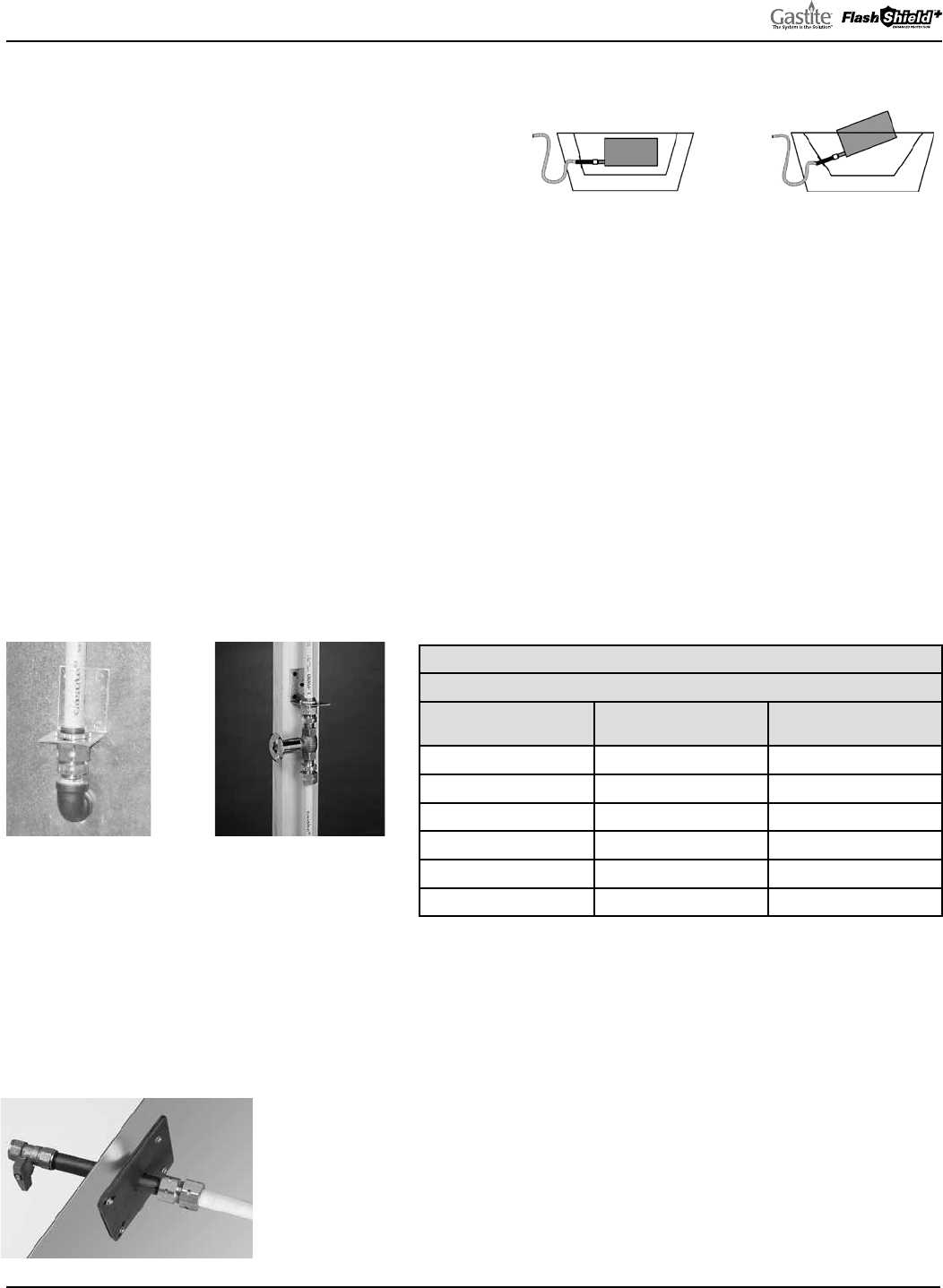
GASTITE DIVISION, TITEFLEX CORPORATION / 1116 Vaughn Parkway / Portland, TN 37148
800.662.0208 / www.gastite.com / [email protected]
64
SECTION 4: INSTALLATION PRACTICES / JANUARY 2020
e Angle Stub is designed to create a secure mounting point or
stub-out for the transition from Gastite/FlashShield
+
CSST to
log-lighters, gas logs, or firebox insert’s controls. Refer to Figure
4-77 below for Angle Stub Installation.
e Angle Stub shall not be connected in such a way that
the log-lighter, gas log, or other components angle out of the
fireplace. To correct for the insertion angle into the firebox,
metal shims such as fender washers can be used. (See the proper
and improper installation Fig. 4-74)
Gastite/FlashShield
+
Mechanical Fittings are approved to be concealed and can be connected directly to a valve controlling
gas flow to a fireplace appliance. e Gastite/FlashShield
+
CSST and valve connection can be installed behind the wall,
beneath the floor, hearth, or behind the brickwork of the fireplace (Fig. 4-76).
Where it is necessary to install Gastite/FlashShield
+
through masonry materials in fireplace construction, the plastic jacket
shall remain intact and the tubing should be routed through sleeving that is appropriate for the application. Sleeving is not
required through ceramic liners in decorative fireplaces and heat generating fireplaces.
Gastite/FlashShield
+
may not be run above the flue within a masonry chimney.
In certain configurations corrugated tubing or flexible appliance connectors feeding a fireplace, firepit or gas log set can
whistle due to gas flow velocity. Acoustics can usually be avoided by restricting Gastite/FlashShield
+
CSST sizes to the
maximum capacity as shown in Table 4-6 below.
TABLE 4-6
FIREPLACE/FIRE PIT
GASTITE/
FLASHSHIELD+ SIZE
EHD BTUH
1/2" 19 45,000
3/4" 23 80,000
1" 31 125,000
1-1/4" 37 195,000
1-1/2" 48 285,000
2" 60 475,000
Fig. 4-74
Improper Angle Stub
Installation
Proper Angle Stub
Installation
Fig. 4-75
Fig. 4-76
Note: Strike Protection
(Floppy) not shown for clarity.
Fig. 4-77
ANGLE STUB-OUT (FIG. 4-77)
1) Attach XR3 female fitting to short end of Stub-Out.
2) Insert long end of Angle Stub-Out through metal insert knockout.
3) Secure Stub-Out utilizing sheet metal screws at the four mounting points.
4) Insert CSST into the female fitting and complete fitting assembly.
5) Refer to Section 4.6.4 (f).
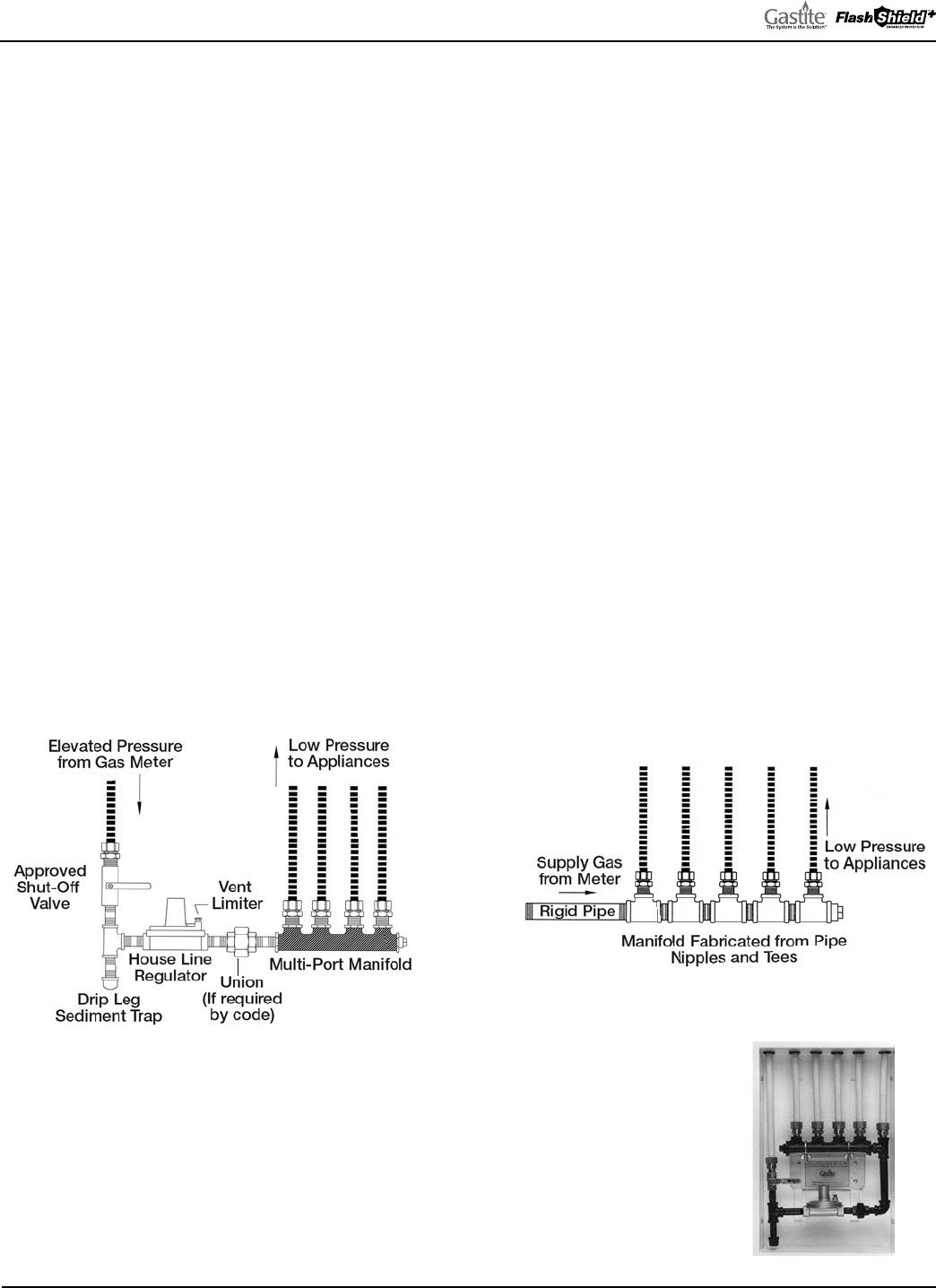
GASTITE DIVISION, TITEFLEX CORPORATION / 1116 Vaughn Parkway / Portland, TN 37148
800.662.0208 / www.gastite.com / [email protected]
65
SECTION 4: INSTALLATION PRACTICES / JANUARY 2020
4.7 MANIFOLD
Manifolds are installed where multiple runs are made from a common location in a parallel arrangement. e manifold
may be manufactured from a one-piece malleable iron or brass casting (Fig. 4-78), a welded fabrication of steel sub-
components or an assembly of approved, malleable iron tees and short nipples (Fig. 4-79). Manifolds must be rigidly
installed. is can be achieved through the use of a mounted manifold bracket or by rigidly piping into a non-movable
gas-piping component.
Depending on the location and available space, different mounting arrangements are permitted. A manifold may be
mounted in any orientation on the surface of an interior wall, between open floor joists, in attic spaces, crawl spaces,
within a partition wall, or inside an enclosure. A manifold assembly without a regulator can be concealed.
e Gastite/FlashShield
+
CSST Capacity Tables include losses for four 90° bends and two end fittings. Tubing runs with
a larger number of bends and/or fittings shall be increased by an equivalent length of tubing to the following equation:
L=1.3n where L is additional length of tubing and n is the number of additional fittings and/or bends. Each port of a
manifold can be taken as an additional fitting. For example: the tube running from the last port of a 3-port manifold
should have 3.9 feet (3 ports/fittings x 1.3) added to the run length for the purpose of sizing. is method is applicable for
all manifolds whose ports are equal or greater in size than the pipe connected to the corresponding port.
e installation of manifold assemblies using a pounds-to-inches regulator must be in accordance with all local codes, and
the following guidelines:
a) A manifold assembly directly integrating a pounds-to-inches regulator shall be installed in an accessible location so that
the regulator can be inspected, maintained and serviced if repair or replacement is required.
b) For manifold systems that use a pounds-to-inches regulator installed behind an access panel, all tubing penetrations in
the cabinet should be sealed, caulked or grommeted. e cabinet must be ventilated through the panel/door and not
into a wall space.
c) Open face cabinets (Fig. 4-80), which open on to the normal room environment, may be
utilized without the need for ventilation or penetration sealing requirements.
Fig. 4-78
Fig. 4-79
Fig. 4-80
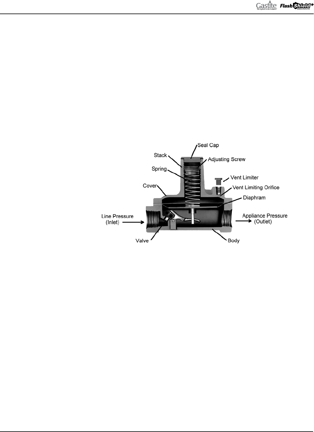
GASTITE DIVISION, TITEFLEX CORPORATION / 1116 Vaughn Parkway / Portland, TN 37148
800.662.0208 / www.gastite.com / [email protected]
66
SECTION 4: INSTALLATION PRACTICES / JANUARY 2020
4.8 PRESSURE REGULATOR
4.8.1 INTRODUCTION (FIG. 4-81)
A Gastite/FlashShield
+
CSST system using line gas pressures above the maximum appliance input rating shall use a
regulator to lower the downstream appliance supply pressure to 1/2 PSI, or less. e regulator shall have a lock-up feature
that will limit the downstream pressure to 1/2 PSI. Line gas pressures at or below the maximum appliance input rating
does do not require the use of a line regulator.
A Line Gas Regulator is defined as a pressure regulator placed in a gas line between the service regulator and the appliance
regulator. Regulators supplied by Gastite Division are designed to supply the highest performance as Line Gas Regulators
and feature precise regulating control from full flow down to pilot flows.
Regulators must be rigidly installed. is can be achieved by rigidly mounting or piping into a rigid gas-piping
component.
Fig. 4-81
4.8.2 SIZING INSTRUCTIONS
Line Pressure Regulator Selection (Tables 4-7 and 4-8).
Line pressure regulators are typically used in a 2 or 5 PSI gas piping installation to reduce supply pressure to the appliance
within required operating ranges (typically 4"WC - 8"WC natural gas or 10"WC - 11"WC LP gas).
Regulators Supplied by Gastite Division:
1) For natural gas, the regulator outlet pressure is set to 8"WC and the appliance runs are sized with a 3"WC pressure drop.
is will allow for 5"WC inlet pressure at the appliance.
2) For propane gas, the regulator outlet pressure is set to 11"WC and the appliance runs are sized with a 0.5"WC drop.
is will allow for a 10.5"WC inlet pressure at the appliance.
To select the correct regulator for pressure regulation, the following information must be established:
• Available inlet pressure range at the regulator inlet.
• Desired outlet pressure.
• Total maximum flow rate vs. regulator model number
(Tables 4-7 and 4-8).
• Largest single appliance flow rate vs. regulator model number
(Tables 4-7 and 4-8).
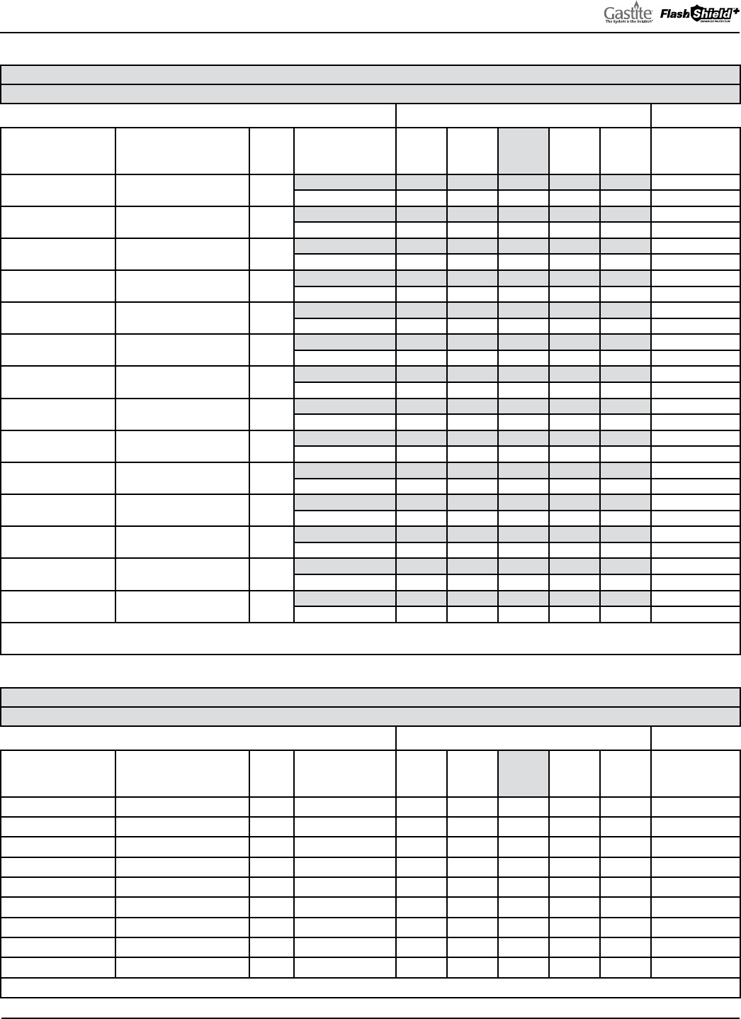
GASTITE DIVISION, TITEFLEX CORPORATION / 1116 Vaughn Parkway / Portland, TN 37148
800.662.0208 / www.gastite.com / [email protected]
67
SECTION 4: INSTALLATION PRACTICES / JANUARY 2020
REGULATOR CAPACITY TABLES
TABLE 4-7. LINE REGULATORS CAPACITY, NATURAL GAS (CFH)
0.60 SPECIFIC GRAVITY GAS, FACTORY OUTLET SETPOINT: 8" W.C., AND 11" W.C
Line Capacity @ Operating Inlet Pressures
Gastite® P/N Mfg. P/N NPT
Outlet Pressure
Setpoint (in. W.C.) 1/2 PSI 3/4 PSI 1 PSI
1-1/2
PSI 2 PSI
Largest Single
Appliance*
(000 BTU/H)
T325-3-44 325-3L-44-NG01 1/2"
8" 150 207 258 258 258
140
11" 114 186 238 258 258 140
T325-5-2 325-5L-44-NG01 1/2"
8" 372 501 516 516 516
425
11" 284 491 516 516 516 425
T325-5-44 325-5L-66-NG01 3/4"
8" 382 537 620 620 620
425
11" 284 465 589 620 620 425
T325-5-3 325-5L-88-NG01 1"
8" 382 537 620 620 620
425
11" 284 465 589 620 620 425
T325-7AL-NG01 325-7AL-1010-NG01 1-1/4"
8" 775 1,033 1,291 1,291 1,291
1,250
11" 542 930 1,162 1,291 1,291 1,250
T325-3L48 325-3L48-44-NG01 1/2"
8" 165 207 207 207 207
200
11" 124 207 207 207 207 200
T325-5AL600 325-5L600-66-NG01 3/4"
8" 356 439 439 439 439
425
11" 269 439 439 439 439 425
T325-7L-210D 325-7AL210D-10-N2 1-1/4"
8" 842 1,157 1,291 1,291 1,291
1,250
11" 599 930 1,136 1,291 1,291 1,250
REG8-300 Type 90 1/2"
8" 160 201 238 258 279
140
11" 134 186 217 248 258 140
REG8-600 Type 95 3/4"
8" 371 407 462 496 526
410
11" 330 372 413 444 496 410
30051-NG 31051 1/2"
8" 306 442 552 710 785
n/a
11" 218 389 511 681 788 n/a
30052-NG 31052 3/4"
8" 369 552 665 888 946
n/a
11" 263 487 616 852 950 n/a
30053-NG 31053 1"
8" 495 718 893 1,154 1,270
n/a
11" 353 633 826 1,108 1,274 n/a
30153-NG 31153 1-1/4"
8" 2,071 2,344 3,735 4,087 5,311
n/a
11" 1,476 2,241 3,457 3,920 5,330 n/a
* Some manufacturers publish reduced capacity of the line regulator, when utilized as a single appliance regulator.
For further information refer to regulator manufacturer's website.
TABLE 4-8. LINE REGULATORS CAPACITY, PROPANE (000 BTU/H)
1.52 SPECIFIC GRAVITY GAS, FACTORY OUTLET SETPOINT: 11" W.C., UNLESS FIELD ADJUSTMENT INDICATED
Line Capacity @ Operating Inlet Pressures
Gastite® P/N Mfg. P/N NPT
Outlet Pressure
Setpoint (in. W.C.) 1/2 PSI 3/4 PSI 1 PSI
1-1/2
PSI 2 PSI
Largest Single
Appliance*
(000 BTU/H)
T325-3-44P 325-3L-44-LP01 1/2" 11" 177 289 368 401 401 225
T325-5-44P 325-5L-66-LP01 3/4" 11" 440 722 916 963 963 684
T325-5-3P 325-5L-88-LP01 1" 11" 440 722 916 963 963 684
REG11-300 Type 90 1/2" 11" 175 284 344 387 387 220
REG11-600 Type 95 3/4" 11" 415 574 669 744 744 500
30051-NG 31051 1/2" field adj. to 11" 341 609 800 1,067 1,235 n/a
30052-LP 31052 3/4" 11" 412 763 965 1,335 1,489 n/a
30053-NG 31053 1" field adj. to 11" 553 992 1,294 1,736 1,996 n/a
30153-NG 31153 1-1/4" field adj. to 11" 2,313 3,512 5,418 6,144 8,354 n/a
* Some manufacturers publish reduced capacity of the line regulator, when utilized as a single appliance regulator.
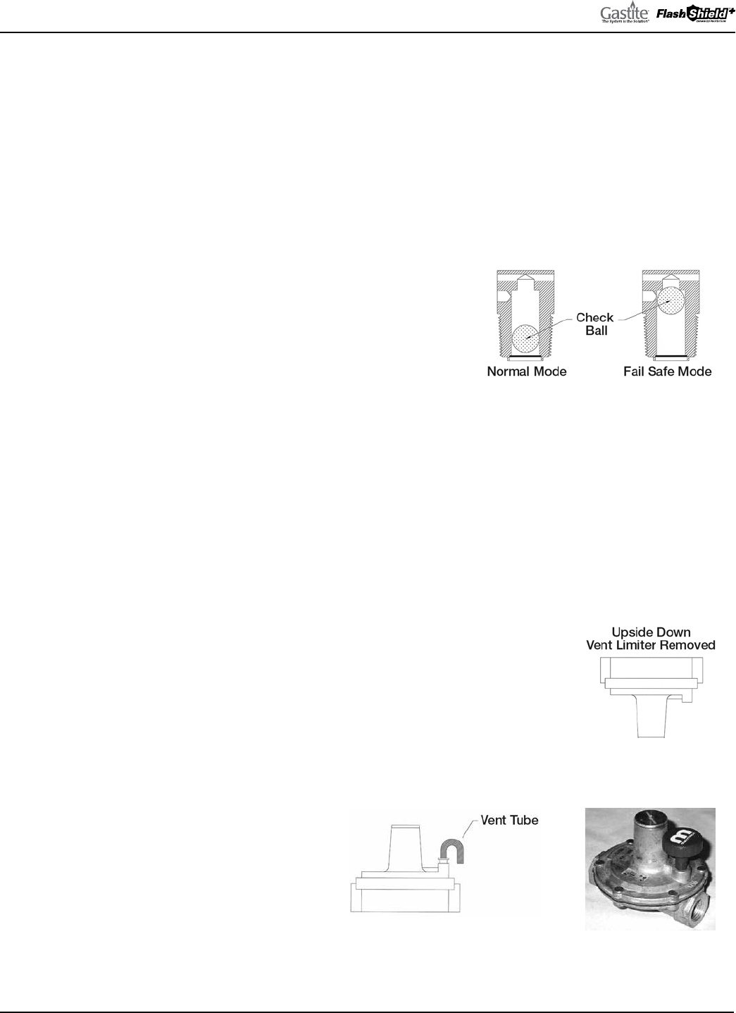
GASTITE DIVISION, TITEFLEX CORPORATION / 1116 Vaughn Parkway / Portland, TN 37148
800.662.0208 / www.gastite.com / [email protected]
68
SECTION 4: INSTALLATION PRACTICES / JANUARY 2020
4.8.3 INSTALLATION
a) e regulator shall be installed in an accessible location with an approved shut-off valve and drip leg on the inlet side
and a union (if required by code) on the outlet side so that it may be inspected, maintained and serviced if repair or
replacement is required. e regulator must be installed with gas flow as indicated by the arrow on the casting.
b) Shut-off valves should be opened and closed slowly. A rapidly opened or closed valve can shock the regulator causing
abnormal behavior.
c) e regulator is suitable for multi-poise mounting. When using a vent-limiting orifice however, the regulator must be
mounted in a horizontal upright position.
d) e vent-limiting orifice (Fig. 4-82) is a fail-safe device that permits
free air movement above the diaphragm during normal operation. In
the unlikely event of a diaphragm rupture, the vent limiting orifice
will limit gas escapement to 1.0 CFH natural gas at 2 PSI and 0.65
CFH LP at 2 PSI. Both values are below the ANSI standard of 2.5
CFH. Note: e vent-limiting orifice does not allow gas to escape to
the environment during operation.
e) Do not leak test the vent orifice with liquid leak test solution. is action will contaminate the internal check ball
mechanism or plug the breathing hole resulting in erratic regulator performance
f) When using a vent-limiting orifice, the maximum inlet pressure is 2 PSI for Propane and 5 PSI for Natural Gas.
g) When using a vent line, the line must be at least the same size as the regulator vent connection for all runs up to 30 feet
and shall be increased one pipe size over its entirety for every additional 30 feet that the vent runs. Vent lines may be
constructed of any approved fuel gas piping, including Gastite/FlashShield
+
CSST. e vent shall be designed to prevent
entry of water, insects or other foreign materials that could cause blockage of the line. Do not vent to appliance flue,
pilot light or building exhaust system.
h) e regulators supplied by Gastite Division have a temperature range limit of -40 to
240 degrees F. e lower temperature limit and rust proof construction design enables
the regulator to be used for outdoor installations. To minimize the potential for
moisture condensation and freezing problems in or around the vent port, the vent-
limiting orifice must be removed for outdoor installations.
OUTDOOR MOUNTING OPTIONS: (FIGURES 4-83 THROUGH 4-85)
e regulator may be mounted upside down with
the open vent port facing down. Consideration
must be taken to ensure there is adequate clearance
for snow buildup.
e regulator may be mounted horizontally, with a
vent tube installed in the venting port. e end of
the tube must be facing downward, and should be
designed to prevent water and foreign material from
causing a blockage. Another alternative is an outdoor
plastic vent protector designed for the regulator.
Fig. 4-82
Fig. 4-83
Fig. 4-84 Fig. 4-85
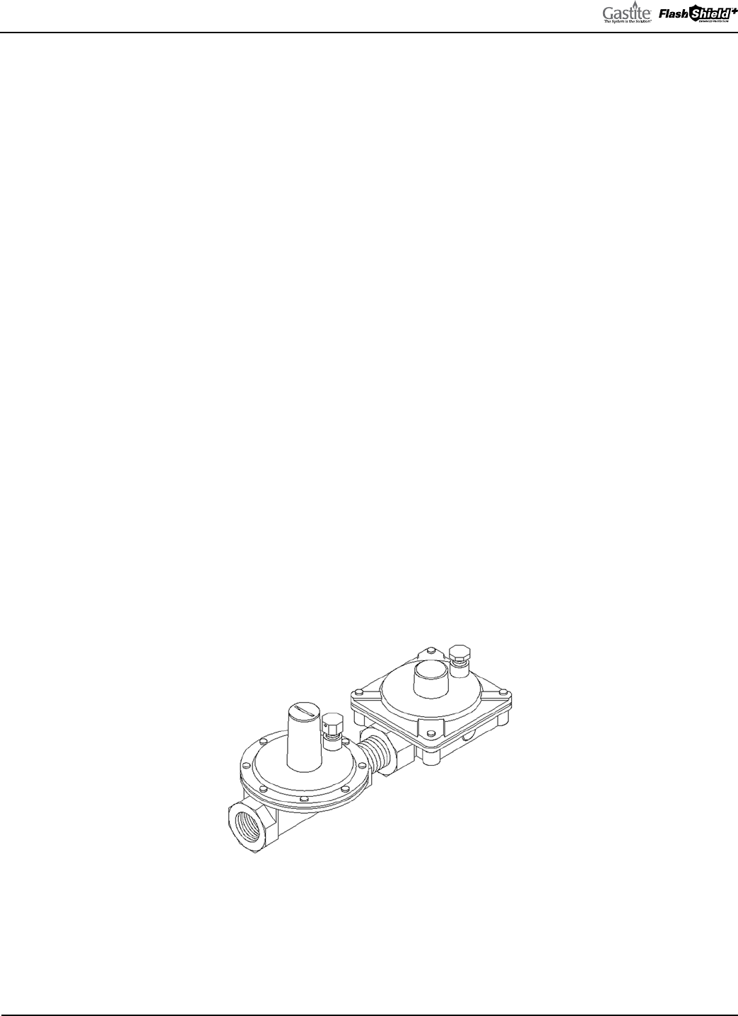
GASTITE DIVISION, TITEFLEX CORPORATION / 1116 Vaughn Parkway / Portland, TN 37148
800.662.0208 / www.gastite.com / [email protected]
69
SECTION 4: INSTALLATION PRACTICES / JANUARY 2020
4.8.4 PERFORMANCE
a) A performance test should be conducted while operating all appliances at full load. is will test if adequate pressure
is reaching each appliance under full-load conditions. To accomplish this, measure the line pressure at the appliance
connection while operating the appliance.
b) e inlet pressure for typical gas appliances under full load conditions should be equal to but not exceeding the
appliance’s recommended inlet pressure range. If these pressure ranges cannot be obtained, a slight adjustment to the
service regulator or the pounds-to-inches regulator may be necessary to increase line pressure.
4.8.5 REGULATOR OUTLET PRESSURE ADJUSTMENT
a) Adjustment can be accomplished by first removing the regulator seal cap to expose the adjusting screw. Turning the
screw clockwise will increase outlet pressure, turning it counter-clockwise will decrease pressure.
b) If spring adjustment will not produce the desired outlet pressure, check to make sure the main supply pressure is
adequate If the main supply pressure is adequate, consult factory for other line-regulator options. Do not continue to
turn regulator adjusting screw clockwise if the outlet pressure readings do not continue to increase. is may result in
over-firing due to loss of pressure control, should there be a subsequent increase in inlet pressure.
c) e line regulators can be adjusted with an outlet pressure ranging between 7 and 11 inches water column. e regulator
must be adjusted according to the manufacturers recommended procedure. A pressure gauge mounted just downstream
of the regulator can monitor the set pressure under various loads.
4.8.6 OVER-PRESSURIZATION PROTECTION
Downstream over-pressure protection must be provided in any gas piping installation where a line-pressure regulator is
utilized for pressures in excess of 2 PSI to supply appliances rated for 1/2 PSI or less inlet pressure. Special line regulators
of suitable control and capacity must be installed in place of the standard line regulator. is regulator contains an integral
over-pressure protection device (OPD) (Fig. 4-86). is special regulator with OPD must be assembled and listed by the
manufacturer in accordance with Z21.80, “Standard for line pressure regulators." Refer to Tables 4-7 and 4-8 for OPD
capacities and sizing.
NOTE: When using regulators other than those specified by Gastite Division for use with the Gastite/FlashShield+ system, careful
consideration must be given to the regulator performance characteristics such as required inlet pressure, flow capacity, the pressure drop
through the regulator and available outlet pressure.
Fig. 4-86
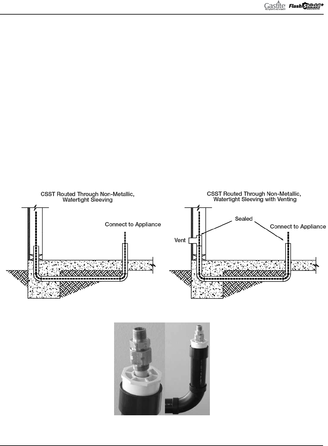
GASTITE DIVISION, TITEFLEX CORPORATION / 1116 Vaughn Parkway / Portland, TN 37148
800.662.0208 / www.gastite.com / [email protected]
70
SECTION 4: INSTALLATION PRACTICES / JANUARY 2020
4.9 UNDERGROUND INSTALLATIONS
a) Gastite/FlashShield
+
CSST shall not be buried directly in the ground or directly embedded in concrete (e.g. slab on
grade construction, patio slabs, foundations and walkways). When it is necessary to bury or embed Gastite/FlashShield
+
CSST, the tubing shall be routed inside a non-metallic, watertight conduit that has an inside diameter at least 1/2 inch
larger than the O.D. of the tubing (Fig. 4-87). For ends of the conduit installed outdoors, the conduit shall be sealed at
any exposed end to prevent water from entering.
b) Venting of the conduit has typically been required because the use of conventional materials such as rigid pipe
has usually resulted in some form of connection or union within the conduit. Unlike rigid pipe however, Gastite/
FlashShield
+
CSST is continuous with only one fitting at each end of the run, and no fittings inside the conduit. As
a result, the possibility of gas build-up due to fitting leaks has been eliminated. erefore, Gastite Division does not
require the sleeving to be vented to the outside of the structure.
If, however, venting is still required, Figure 4-88 below depicts gas piping installed within plastic sleeving that is vented
to the outdoors. Other possible venting routes, such as the attic and roof, may also be considered but must be reviewed
with the local administrative authority, and must prevent the entry of water and foreign objects.
For ends of Gastite/FlashShield
+
CSST exiting the plastic sleeving, a termination fitting (XR3TRM-SIZE-NF) threaded
into an end “plug”, can be used to provide a stable platform for attachment (Fig. 4-89).
Fig. 4-87 Fig. 4-88
Fig. 4-89
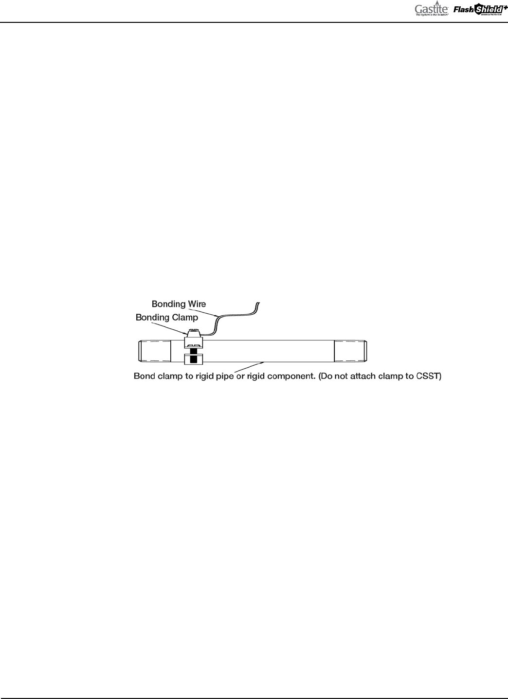
GASTITE DIVISION, TITEFLEX CORPORATION / 1116 Vaughn Parkway / Portland, TN 37148
800.662.0208 / www.gastite.com / [email protected]
71
SECTION 4: INSTALLATION PRACTICES / JANUARY 2020
4.10 ELECTRICAL BONDING OF GASTITE
®
/FLASHSHIELD
+
CSST
a) Unlike Gastite, there are no additional bonding requirements for FlashShield
+
imposed by the manufacturer’s
installation instructions. FlashShield
+
is to be bonded in accordance with the National Electrical Code NFPA 70 Article
250.104 and Canadian Electrical Code, CSA-C22.1, in the same manner as the minimum requirements for rigid metal
piping. However, installers must always adhere to any local requirements that may conflict with these instructions.
b) Direct bonding of Gastite yellow CSST is required for all gas-piping systems incorporating Gastite CSST whether or not
the connected gas equipment is electrically powered. is requirement is for single-family and multi-family buildings.
A person knowledgeable in electrical system design, the local electrical code and these requirements should specify the
bonding for commercial applications.
Gastite yellow CSST installed inside or attached to a building shall be electrically continuous and direct bonded to the
electrical ground system of the structure in which it is installed. e gas piping system shall be considered to be direct-
bonded when installed in accordance with the following:
• A single bond clamp attachment to rigid pipe or rigid component at any point within the gas piping system
- Bond clamp attachment downstream of individual gas meter or 2nd stage regulator for propane systems, and in
accessible location
- Metallic contact is required (remove paint or plating on steel pipe)
- Bonding clamp listed to UL 467
Fig. 4-90
• Bonding conductor is #6 AWG copper (minimum) or equivalent, and not exceeding 75 feet in length
- e shortest practical bond wire length will improve the effectiveness of the direct bond
• e bonding conductor is permanently and directly connected to the electrical service grounding electrode system of
the premises. is connection can be made at either:
- Bonding buss
- Grounding electrode conductor
- Grounding electrode
• Any additional grounding electrodes used shall be bonded to the electrical service grounding electrode system
• Direct bonding to be performed by a person qualified to do so per local ordinances
• e bonding conductor shall be installed and protected in accordance with:
- National Electrical Code, NFPA 70, (NEC)
- Canadian Electrical Code, CSA-C22.1, (CEC)
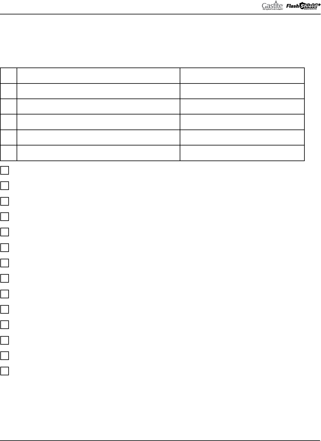
GASTITE DIVISION, TITEFLEX CORPORATION / 1116 Vaughn Parkway / Portland, TN 37148
800.662.0208 / www.gastite.com / [email protected]
72
SECTION 5: INSPECTION, REPAIR & REPLACEMENT / JANUARY 2020
SECTION 5.0 INSPECTION, REPAIR & REPLACEMENT
5.1 MINIMUM INSPECTION REQUIREMENTS
GASTITE/FLASHSHIELD
+
INSTALLATION CHECKLIST
Date: Elevated Pressure: Yes No
Contractor: Comments:
Address:
Qualified installer with Certification Card
Components from Gastite
Strike protection
System Sizing
Connected to fixed appliance only; Flexible connector for moveable appliances
Regulator isolated or removed for pressure test
Regulator horizontal and upright when using vent limiter
Regulator installed in an accessible location with shut-off valve and drip leg mounted ahead of regulator
Protective jacket kept in place
Sleeved for underground and through masonry
Supported but not restricted
Bonded per Section 4.10.
Installation within a chase restrictions per Section 4.3.9.
Physical separation per Sections 4.3.1 and 4.3.2

GASTITE DIVISION, TITEFLEX CORPORATION / 1116 Vaughn Parkway / Portland, TN 37148
800.662.0208 / www.gastite.com / [email protected]
73
SECTION 5: INSPECTION, REPAIR & REPLACEMENT / JANUARY 2020
5.2 INSTALLATION CHECKLIST DESCRIPTION
Corrugated Stainless Steel Tubing (CSST) has been design certified by the Canadian Standards Association since 1990 for
use as a fuel gas piping system. Gastite/FlashShield
+
CSST has been tested per ANSI LC1/CSA 6.26 as required for ap-
proval and as an approved gas piping material in the National Fuel Gas Code-NFPA 54 & 58, the International Fuel Gas
Code-ICC, and with the Uniform Plumbing Code-IAPMO, and Natural Gas & Propane installation code B149.1.
APPROVAL: CONDITIONS AND REQUIREMENTS
A flexible gas piping system using Gastite/FlashShield
+
CSST must be installed in accordance with all local building codes
and the manufacturer’s instructions. e following checklist is designed to assist the local administrative authority to per-
form an inspection of a fuel gas piping system using corrugated stainless steel tubing.
1) Gastite/FlashShield
+
flexible gas piping may only be installed by a qualified installer who has successfully completed
the manufacturer's certification training program. A manufacturer’s certification card is required to purchase and install
Gastite/FlashShield
+
flexible gas piping.
2) Gastite/FlashShield
+
CSST routed in a location which is concealed, constrained and within 3 inches of a potential
threat must be protected against damage using protection devices listed in the manufacturer’s Design and Installation
Guide.
3) Gastite/FlashShield
+
CSST should not be connected to moveable appliances. Connections to moveable appliances such
as ranges and clothes dryers should be accomplished with a flexible appliance connector.
4) Regulators are suitable for multi-poise mounting. When using a vent-limiting device however, the regulator must be
mounted in a horizontal upright position.
5) Gastite tubing shall not be installed within a chase and/or enclosure that includes a metallic appliance vent and/or a
metallic chimney line that protrudes through and/or past the roof.
6) When installed outdoors, the external jacket shall remain intact as much as possible. Exposed portions of the stainless
steel tubing or aluminum mesh shall be wrapped to provide protection from corrosive threats.
7) For installations buried underground, under concrete/asphalt or embedded in concrete, Gastite/FlashShield
+
CSST
must be routed in a non-metallic watertight conduit which has an inside diameter at least 1/2 in. larger than the
outside diameter of the tubing. Under concrete/asphalt slab, sleeved CSST must be buried in accordance with all local
codes. No mechanical joints are permitted within the conduit.
8) Installation must be properly supported to not only keep the job professional and organized but also to prevent excess
strain on the bends and fittings. Supports installed in addition to the practices outlined by Gastite Division, restricts
the tubing and increases susceptibility to strike damage.
9) Gas piping systems must be properly bonded to the structure's electrical service. A qualified professional following the
NEC approved methods as outlined in Section 4.10 shall perform the bonding installation.
10) Gastite CSST must be physically separated from other continuous metallic systems in accordance with Section 4.3 of
this guide.
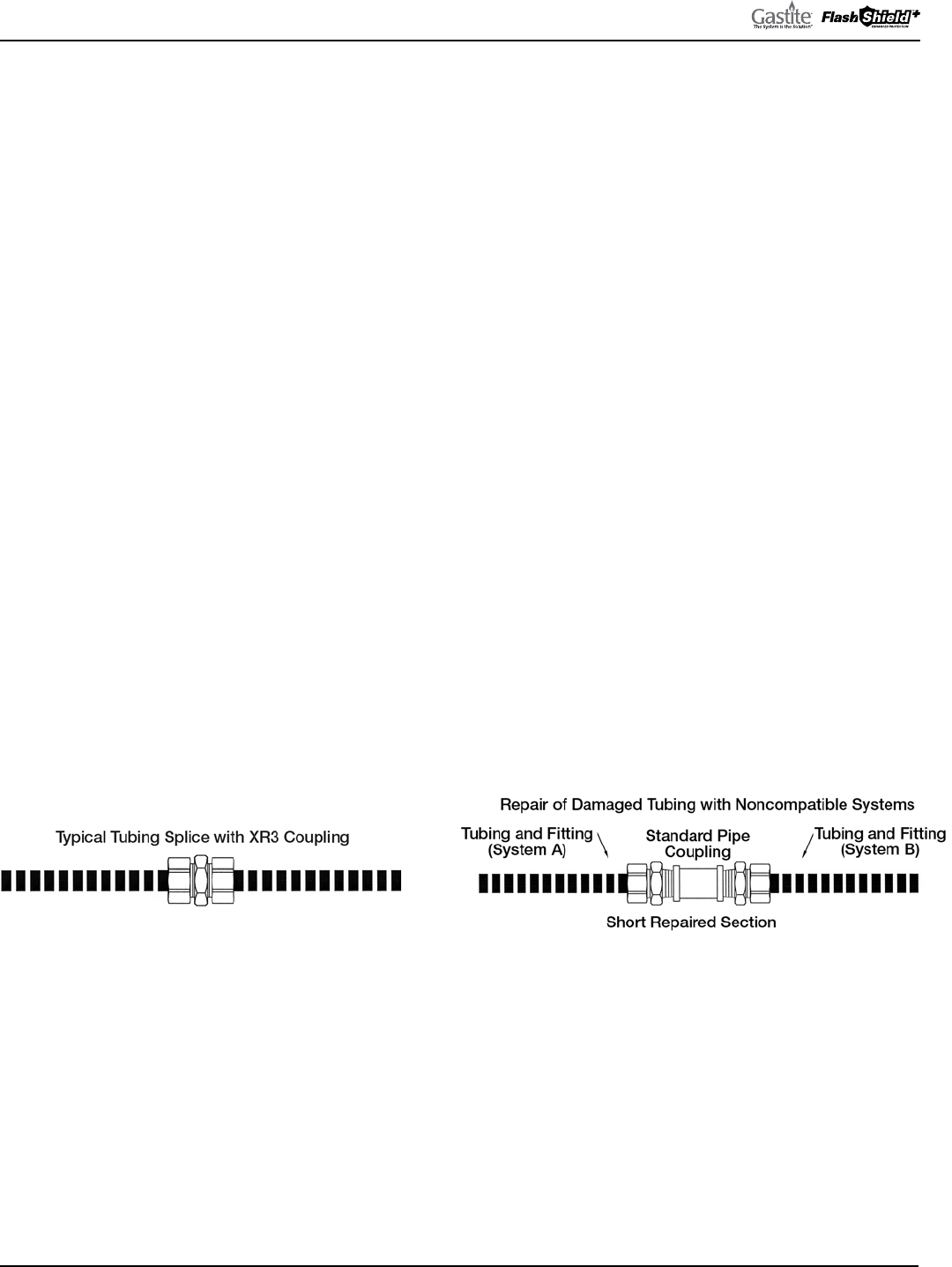
GASTITE DIVISION, TITEFLEX CORPORATION / 1116 Vaughn Parkway / Portland, TN 37148
800.662.0208 / www.gastite.com / [email protected]
74
SECTION 5: INSPECTION, REPAIR & REPLACEMENT / JANUARY 2020
5.3 REPAIR OF DAMAGED CSST
5.3.1 DETERMINE DAMAGE
Crushed, dented or kinked tubing may result in restricted flow conditions. Use the following guidelines to determine the
severity of damage and whether repair or replacement is necessary.
a) Gastite/FlashShield
+
CSST gas tubing must be repaired if damaged by puncture of any kind, e.g. nails, screws, drill bits, etc.
b) No repairs or replacement of the tubing is necessary if the Gastite/FlashShield
+
CSST tubing is only slightly dented due
to impact or crushing and the overall crush depth is less than 1/3 the diameter of the tubing. Minimal flow reduction will
occur at this limited damage level.
c) Repair or replacement is necessary if the overall crush depth is greater than 1/3 the diameter of the tubing. Restricted flow
may occur at this damage level.
d) Gastite/FlashShield
+
CSST tubing bent beyond its minimum bend radius so that a crease or kink remains must be
repaired. Restricted flow may occur at this damage level.
5.3.2 METHOD OF REPAIR
A line splice can be made, but if the tubing run is short and easily accessible, the preferred repair method is to replace the
entire length. Often, a tubing run can be replaced faster than repairing the damaged section. e Gastite/FlashShield
+
mechanical joint fittings can be removed and easily re-attached. is is the preferred method because it does not add any
additional fitting joints to the system.
Where repairs or replacements involve only the Gastite/FlashShield
+
CSST, the tubing can be joined with standard pipe
couplings or Gastite/FlashShield
+
CSST coupling (Fig. 5-1).
Where repairs or replacements involve CSST systems of different manufacturers, the systems can be joined through standard
pipe couplings and each manufacturer’s recommended CSST fitting (Fig. 5-2).
5.3.3 FLASHSHIELD
+
JACKET REPAIR
Scuffing, scraping, or tearing of the outer polymer jacket layer may occur during installation. Within limits this condition
will not affect the performance of FlashShield
+
CSST as long as the middle layer (metallic shield) and the bottom layer
(semi-conductive polyethylene) remain in normal condition.
If a tear in the outer jacket is greater than 1/2" in length, Gastite recommends wrapping the tear area with electrical tape
or self-bonding silicone tape, to provide continued protection to the metal shield layer. If the metal shield layer tears for a
length great than 1/2", the affected area must be cut out and replaced using appropriate methods. If the affected area (of
greater than 1/2" metal shield tear length) cannot be cut out and replaced, the FlashShield
+
CSST system shall be treated
like a yellow Gastite CSST system with regard to Gastite yellow CSST isolation/separation requirements (sec. 4.3), and
direct-bonding (sec. 4.10).
Fig. 5-1
Fig. 5-2
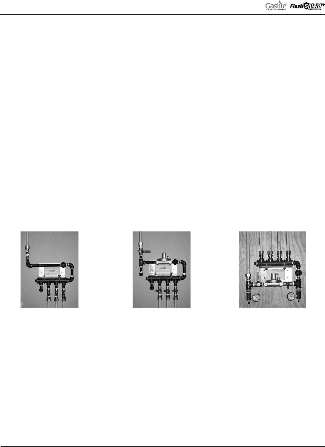
GASTITE DIVISION, TITEFLEX CORPORATION / 1116 Vaughn Parkway / Portland, TN 37148
800.662.0208 / www.gastite.com / [email protected]
75
SECTION 6: PRESSURE/LEAKAGE TESTING / JANUARY 2020
SECTION 6.0 PRESSURE/LEAKAGE TESTING
6.1 GENERAL GUIDELINES FOR PRESSURE TESTING
a) e final installation must be inspected and tested for leaks in accordance with the local/state codes. In the absence of
local codes, installation must be in accordance with the current edition of the National Fuel Gas Code, ANSI Z223.1/
NFPA-54 (USA), or Installation Codes CSA-B149.1 (Canada). Pressure testing must comply with these guidelines or
local codes. When local codes are more stringent, local codes must be followed.
b) Pressure testing must be performed during rough construction of the facility (before interior walls are finished). is will
permit a more complete inspection of the piping system during the pressure testing.
c) Do not connect appliances or pressurize with fuel gas until after the pressure test has been passed.
d) All gas outlets for appliance connections should be capped during pressure testing.
6.2 ELEVATED PRESSURE SYSTEMS
If an elevated pressure system requires a pressure test of 10 PSI or greater, the regulator must be removed or isolated prior
to pressure testing.
e test may be performed as a one-part test replacing the regulator with a suitable jumper pipe length for pressure testing
the entire system (Figures 6-1 and 6-2).
Or a two-part test may be performed as shown in Figure 6-3:
• e first test is performed on the elevated pressure section, between the meter connection and the pounds-to-inches line
regulator.
• e second test is performed on the low-pressure section, between the outlet of the pounds-to-inches line regulator and the
gas appliance outlets.
• For a two-part test, it is important to remember to close both gas shut-off valves to avoid damage to the regulator.
• When opening the shut-off valves it is important to open them slowly. A quickly opened valve can shock the regulator and
cause abnormal regulator behavior.
Fig. 6-1 Fig. 6-2 Fig. 6-3

GASTITE DIVISION, TITEFLEX CORPORATION / 1116 Vaughn Parkway / Portland, TN 37148
800.662.0208 / www.gastite.com / [email protected]
76
SECTION 6: PRESSURE/LEAKAGE TESTING / JANUARY 2020
6.3 APPLIANCE CONNECTION LEAKAGE CHECK PROCEDURE
After the final pressure test, inspection and final construction is complete (finished interior walls), connect the appliances
to the system. is connection can be made using an approved flexible connector for movable appliances, or with Gastite/
FlashShield
+
CSST tubing or rigid black pipe for fixed appliances. Turn the gas on at the meter and inspect for leakage
before operating the appliances.
a) Some leak check solutions may be corrosive. When leak checking the FlashShield
+
system including (but not limited to)
the stainless steel tubing, brass fittings and valves, stub-outs and connections made at the appliances, the leak check solu-
tion must be labeled as non-corrosive.
b) Before placing the appliances in operation, the tubing system should be purged. is displaces the air in the system with
fuel gas. Be sure to vent into a well-ventilated area.
NOTE: Leak test solutions may cause corrosion in some types of material in the gas tubing system, be sure to water
rinse after the test and thoroughly dry all contacted material. Also, the vent limiter should not be leak tested with a
liquid test solution. is will contaminate the internal ball check mechanism or plug the breathing hole, resulting in
erratic regulator operation.
NOTE: Near maximum allowable pressure test levels listed on the Gastite/FlashShield
+
specification sheets (Sec-
tion 9.2), the tubing may move/distort which can affect tubing supports. Once the pressure is released the tubing
should return to relatively the same position. Use caution when pressure testing and do not exceed the maximum
test pressure.
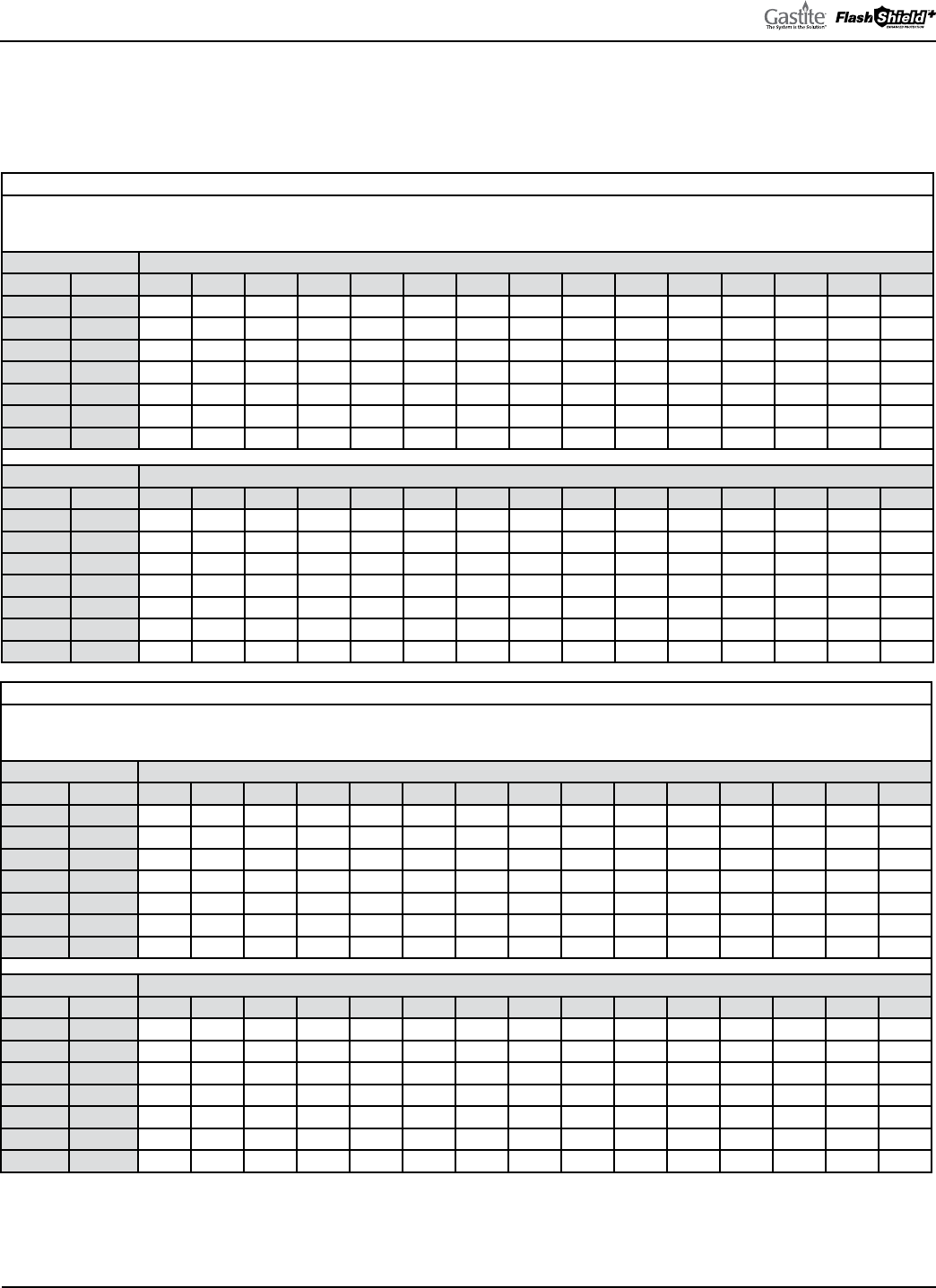
GASTITE DIVISION, TITEFLEX CORPORATION / 1116 Vaughn Parkway / Portland, TN 37148
800.662.0208 / www.gastite.com / [email protected]
77
SECTION 7: SIZING TABLES & PRESSURE DROP CHARTS / JANUARY 2020
SECTION 7.0 SIZING TABLES & PRESSURE DROP CHARTS
FOR GASTITE AND FLASHSHIELD
+
CSST
7.1 CSST CAPACITY TABLES—NATURAL GAS
Table 7-1
Maximum Capacity of Gastite/FlashShield
+
Flexible Gas Piping in Cubic Feet Per Hour of Natural Gas
with a Gas Pressure of 0.5 PSI or Less and a Pressure Drop of 0.5"WC
(based on a 0.60 specific gravity gas)
TUBING TUBING LENGTH (FT)
EHD Size 5 10 15 20 25 30 40 50 60 70 80 90 100 125 150
13 3/8" 47 32 26 22 20 18 15 14 13 12 11 10 10 8 8
19 1/2" 131 93 76 66 59 54 47 42 38 36 33 32 30 27 24
23 3/4" 251 183 152 133 120 110 97 87 80 75 70 67 63 57 53
31 1" 578 415 341 297 267 244 213 191 175 163 153 144 137 123 113
37 1-1/4" 871 620 508 441 396 362 314 282 258 239 224 211 201 180 164
48 1-1/2" 1834 1304 1068 926 830 759 658 590 539 500 468 442 419 376 343
60 2" 3874 2711 2199 1896 1690 1539 1327 1183 1077 994 928 874 827 737 671
TUBING TUBING LENGTH (FT)
EHD Size 200 250 300 400 500 600 700 800 900 1000 1100 1200 1300 1400 1500
13 3/8" 7 6 5 5 4 4 3 3 3 3 3 3 2 2 2
19 1/2" 21 19 17 15 14 12 11 11 10 10 9 9 8 8 8
23 3/4" 46 42 38 34 30 28 26 24 23 22 21 20 20 19 18
31 1" 98 88 81 70 63 58 54 50 48 45 43 42 40 39 37
37 1-1/4" 143 128 117 102 91 83 77 72 68 65 62 59 57 55 53
48 1-1/2" 298 267 244 212 190 173 161 150 142 135 129 123 118 114 110
60 2" 579 516 470 405 361 329 304 283 267 253 240 230 221 212 205
Table 7-2
Maximum Capacity of Gastite/FlashShield
+
Flexible Gas Piping in Cubic Feet Per Hour of Natural Gas
with a Gas Pressure of 0.5 PSI or Less and a Pressure Drop of 1.0"WC
(based on a 0.60 specific gravity gas)
TUBING TUBING LENGTH (FT)
EHD Size 5 10 15 20 25 30 40 50 60 70 80 90 100 125 150
13 3/8" 67 47 38 32 29 26 22 20 18 17 15 15 14 12 11
19 1/2" 185 131 107 93 83 76 66 59 54 50 47 44 42 38 34
23 3/4" 345 251 209 183 165 152 133 120 110 103 97 92 87 79 72
31 1" 807 578 476 415 372 341 297 267 244 227 213 201 191 172 157
37 1-1/4" 1224 871 714 620 556 508 441 396 362 336 314 297 282 253 231
48 1-1/2" 2581 1834 1502 1304 1168 1068 926 830 759 703 658 621 590 528 483
60 2" 5538 3874 3144 2711 2416 2199 1896 1690 1539 1421 1327 1249 1183 1054 960
TUBING TUBING LENGTH (FT)
EHD Size 200 250 300 400 500 600 700 800 900 1000 1100 1200 1300 1400 1500
13 3/8" 10 8 8 7 6 5 5 5 4 4 4 4 4 3 3
19 1/2" 30 27 24 21 19 17 16 15 14 14 13 12 12 11 11
23 3/4" 63 57 53 46 42 38 36 34 32 30 29 28 27 26 25
31 1" 137 123 113 98 88 81 75 70 67 63 60 58 56 54 52
37 -1/4" 201 180 164 143 128 117 109 102 96 91 87 83 80 77 75
48 1-1/2" 419 376 343 298 267 244 226 212 200 190 181 173 167 161 155
60 2" 827 737 671 579 516 470 434 405 381 361 344 329 315 304 293
Tables include losses for four 90° bends and two end fittings. Tubing runs with a larger number of bends and/or fittings shall be increased by an equivalent
length of tubing to the following equation: L=1.3n where L is additional length of tubing and n is the number of additional fittings and/or bends.
GASTITE DIVISION, TITEFLEX CORPORATION / 1116 Vaughn Parkway / Portland, TN 37148
800.662.0208 / www.gastite.com / [email protected]
78
SECTION 7: SIZING TABLES & PRESSURE DROP CHARTS / JANUARY 2020
Table 7-3
Maximum Capacity of Gastite/FlashShield
+
Flexible Gas Piping in Cubic Feet Per Hour of Natural Gas
with a Gas Pressure of 0.5 PSI or Less and a Pressure Drop of 1.5"WC
(based on a 0.60 specific gravity gas)
Tubing Tubing Length (ft)
EHD Size 5 10 15 20 25 30 40 50 60 70 80 90 100 125 150
13 3/8" 83 58 47 40 36 32 28 25 22 21 19 18 17 15 14
19 1/2" 226 160 131 114 102 93 81 72 66 61 57 54 51 46 42
23 3/4" 416 303 251 220 199 183 160 145 133 124 116 110 105 95 87
31 1" 981 703 578 504 452 415 361 324 297 276 259 244 232 209 191
37 1-1/4" 1493 1063 871 757 678 620 539 483 441 409 383 362 344 308 282
48 1-1/2" 3152 2240 1834 1592 1426 1304 1131 1014 926 859 804 759 720 645 590
60 2" 6825 4775 3874 3340 2978 2711 2337 2083 1896 1752 1635 1539 1457 1299 1183
Tubing Tubing Length (ft)
EHD Size 200 250 300 400 500 600 700 800 900 1000 1100 1200 1300 1400 1500
13 3/8" 12 11 10 8 7 7 6 6 5 5 5 5 4 4 4
19 1/2" 37 33 30 26 23 21 20 18 17 17 16 15 15 14 14
23 3/4" 76 69 63 56 50 46 43 40 38 37 35 34 32 31 30
31 1" 167 150 137 119 107 98 91 86 81 77 73 70 68 65 63
37 1-1/4" 245 219 201 174 156 143 132 124 117 111 106 102 98 94 91
48 1-1/2" 512 459 419 364 326 298 276 259 244 232 221 212 204 196 190
60 2" 1020 909 827 713 636 579 535 499 470 445 424 405 389 374 361
Table 7-4
Maximum Capacity of Gastite/FlashShield
+
Flexible Gas Piping in Cubic Feet Per Hour of Natural Gas
with a Gas Pressure of 0.5 PSI or Less and a Pressure Drop of 2.0"WC
(based on a 0.60 specific gravity gas)
Tubing Tubing Length (ft)
EHD Size 5 10 15 20 25 30 40 50 60 70 80 90 100 125 150
13 3/8" 97 67 54 47 41 38 32 29 26 24 22 21 20 18 16
19 1/2" 260 185 151 131 118 107 93 83 76 71 66 62 59 53 49
23 3/4" 475 345 287 251 227 209 183 165 152 141 133 126 120 108 100
31 1" 1126 807 664 578 520 476 415 372 341 317 297 281 267 240 220
37 1-1/4" 1719 1224 1003 871 781 714 620 556 508 471 441 417 396 355 324
48 1-1/2" 3632 2581 2114 1834 1643 1502 1304 1168 1068 989 926 874 830 744 680
60 2" 7915 5538 4493 3874 3453 3144 2711 2416 2199 2031 1896 1785 1690 1507 1372
Tubing Tubing Length (ft)
EHD Size 200 250 300 400 500 600 700 800 900 1000 1100 1200 1300 1400 1500
13 3/8" 14 12 11 10 8 8 7 7 6 6 6 5 5 5 5
19 1/2" 42 38 34 30 27 24 23 21 20 19 18 17 17 16 16
23 3/4" 87 79 72 63 57 53 49 46 44 42 40 38 37 36 35
31 1" 191 172 157 137 123 113 105 98 93 88 84 81 78 75 73
37 1-1/4" 282 253 231 201 180 164 152 143 135 128 122 117 113 109 105
48 1-1/2" 590 528 483 419 376 343 318 298 281 267 255 244 235 226 219
60 2" 1183 1054 960 827 737 671 620 579 545 516 491 470 451 434 419
Tables include losses for four 90° bends and two end fittings. Tubing runs with a larger number of bends and/or fittings shall be increased by an equivalent
length of tubing to the following equation: L=1.3n where L is additional length of tubing and n is the number of additional fittings and/or bends.
GASTITE DIVISION, TITEFLEX CORPORATION / 1116 Vaughn Parkway / Portland, TN 37148
800.662.0208 / www.gastite.com / [email protected]
79
SECTION 7: SIZING TABLES & PRESSURE DROP CHARTS / JANUARY 2020
Table 7-5
Maximum Capacity of Gastite/FlashShield
+
Flexible Gas Piping in Cubic Feet Per Hour of Natural Gas
with a Gas Pressure of 0.5 PSI or Less and a Pressure Drop of 3.0"WC
Line Regulator Outlet (8 in.WC ) (based on a 0.60 specific gravity gas)
Tubing Tubing Length (ft)
EHD Size 5 10 15 20 25 30 40 50 60 70 80 90 100 125 150
13 3/8" 120 83 67 58 51 47 40 36 32 30 28 26 25 22 20
19 1/2" 318 226 185 160 144 131 114 102 93 86 81 76 72 65 59
23 3/4" 572 416 345 303 273 251 220 199 183 170 160 152 145 130 120
31 1" 1368 981 807 703 631 578 504 452 415 385 361 341 324 291 267
37 1-1/4" 2097 1493 1224 1063 953 871 757 678 620 575 539 508 483 433 396
48 1-1/2" 4435 3152 2581 2240 2007 1834 1592 1426 1304 1208 1131 1068 1014 908 830
60 2" 9755 6825 5538 4775 4256 3874 3340 2978 2711 2504 2337 2199 2083 1857 1690
Tubing Tubing Length (ft)
EHD Size 200 250 300 400 500 600 700 800 900 1000 1100 1200 1300 1400 1500
13 3/8" 17 15 14 12 11 10 9 8 8 7 7 7 6 6 6
19 1/2" 51 46 42 37 33 30 28 26 24 23 22 21 20 20 19
23 3/4" 105 95 87 76 69 63 59 56 53 50 48 46 44 43 42
31 1" 232 209 191 167 150 137 127 119 113 107 102 98 95 91 88
37 1-1/4" 344 308 282 245 219 201 186 174 164 156 149 143 137 132 128
48 1-1/2" 720 645 590 512 459 419 389 364 343 326 311 298 286 276 267
60 2" 1457 1299 1183 1020 909 827 764 713 671 636 605 579 555 535 516
Table 7-6
Maximum Capacity of Gastite/FlashShield
+
Flexible Gas Piping in Cubic Feet Per Hour of Natural Gas
with a Gas Pressure of 0.5 PSI or Less and a Pressure Drop of 4.0"WC
(based on a 0.60 specific gravity gas)
Tubing Tubing Length (ft)
EHD Size 5 10 15 20 25 30 40 50 60 70 80 90 100 125 150
13 3/8" 140 97 78 67 60 54 47 41 38 35 32 30 29 25 23
19 1/2" 366 260 213 185 165 151 131 118 107 100 93 88 83 75 68
23 3/4" 653 475 394 345 312 287 251 227 209 194 183 173 165 149 137
31 1" 1571 1126 927 807 725 664 578 520 476 442 415 392 372 334 306
37 1-1/4" 2415 1719 1409 1224 1097 1003 871 781 714 662 620 585 556 498 456
48 1-1/2" 5110 3632 2974 2581 2312 2114 1834 1643 1502 1392 1304 1230 1168 1046 956
60 2" 11314 7915 6423 5538 4936 4493 3874 3453 3144 2904 2711 2551 2416 2154 1960
Tubing Tubing Length (ft)
EHD Size 200 250 300 400 500 600 700 800 900 1000 1100 1200 1300 1400 1500
13 3/8" 20 18 16 14 12 11 10 10 9 8 8 8 7 7 7
19 1/2" 59 53 49 42 38 34 32 30 28 27 26 24 24 23 22
23 3/4" 120 108 100 87 79 72 67 63 60 57 55 53 51 49 48
31 1" 267 240 220 191 172 157 146 137 130 123 118 113 109 105 101
37 1-1/4" 396 355 324 282 253 231 214 201 189 180 172 164 158 152 147
48 1-1/2" 830 744 680 590 528 483 448 419 396 376 358 343 330 318 308
60 2" 1690 1507 1372 1183 1054 960 886 827 779 737 702 671 644 620 598
Tables include losses for four 90° bends and two end fittings. Tubing runs with a larger number of bends and/or fittings shall be increased by an equivalent
length of tubing to the following equation: L=1.3n where L is additional length of tubing and n is the number of additional fittings and/or bends.

GASTITE DIVISION, TITEFLEX CORPORATION / 1116 Vaughn Parkway / Portland, TN 37148
800.662.0208 / www.gastite.com / [email protected]
80
SECTION 7: SIZING TABLES & PRESSURE DROP CHARTS / JANUARY 2020
Table 7-7
Maximum Capacity of Gastite/FlashShield
+
Flexible Gas Piping in Cubic Feet Per Hour of Natural Gas
with a Gas Pressure of 0.5 PSI or Less and a Pressure Drop of 5.0"WC
(based on a 0.60 specific gravity gas)
Tubing Tubing Length (ft)
EHD Size 5 10 15 20 25 30 40 50 60 70 80 90 100 125 150
13 3/8" 157 109 88 76 67 61 52 47 42 39 36 34 32 29 26
19 1/2" 409 290 238 206 185 169 146 131 120 111 104 98 93 83 76
23 3/4" 723 526 437 383 345 318 278 251 231 215 202 192 183 165 152
31 1" 1749 1254 1032 898 807 739 644 578 530 492 461 436 415 372 341
37 1-1/4" 2694 1918 1572 1365 1224 1119 972 871 797 739 692 653 620 556 508
48 1-1/2" 5704 4054 3320 2881 2581 2359 2048 1834 1677 1554 1455 1373 1304 1168 1068
60 2" 12692 8880 7205 6213 5538 5041 4346 3874 3527 3257 3041 2862 2711 2416 2199
Tubing Tubing Length (ft)
EHD Size 200 250 300 400 500 600 700 800 900 1000 1100 1200 1300 1400 1500
13 3/8" 22 20 18 15 14 13 12 11 10 10 9 9 8 8 8
19 1/2" 66 59 54 47 42 38 36 33 32 30 29 27 26 25 24
23 3/4" 133 120 110 97 87 80 75 70 67 63 61 58 56 54 53
31 1" 297 267 244 213 191 175 163 153 144 137 131 126 121 117 113
37 1-1/4" 441 396 362 314 282 258 239 224 211 201 191 183 176 170 164
48 1-1/2" 926 830 759 658 590 539 500 468 442 419 400 383 368 355 343
60 2" 1896 1690 1539 1327 1183 1077 994 928 874 827 788 753 723 696 671
Table 7-8
Maximum Capacity of Gastite/FlashShield
+
Flexible Gas Piping in Cubic Feet Per Hour of Natural Gas
with a Gas Pressure of 0.5 PSI or Less and a Pressure Drop of 6.0"WC
(based on a 0.60 specific gravity gas)
Tubing Tubing Length (ft)
EHD Size 5 10 15 20 25 30 40 50 60 70 80 90 100 125 150
13 3/8" 173 120 97 83 74 67 58 51 47 43 40 38 36 32 29
19 1/2" 447 318 260 226 202 185 160 144 131 122 114 107 102 91 83
23 3/4" 787 572 475 416 376 345 303 273 251 234 220 209 199 179 165
31 1" 1909 1368 1126 981 881 807 703 631 578 537 504 476 452 406 372
37 1-1/4" 2946 2097 1719 1493 1338 1224 1063 953 871 808 757 714 678 608 556
48 1-1/2" 6240 4435 3632 3152 2824 2581 2240 2007 1834 1700 1592 1502 1426 1278 1168
60 2" 13943 9755 7915 6825 6083 5538 4775 4256 3874 3578 3340 3144 2978 2654 2416
Tubing Tubing Length (ft)
EHD Size 200 250 300 400 500 600 700 800 900 1000 1100 1200 1300 1400 1500
13 3/8" 25 22 20 17 15 14 13 12 11 11 10 10 9 9 8
19 1/2" 72 65 59 51 46 42 39 37 34 33 31 30 29 28 27
23 3/4" 145 130 120 105 95 87 81 76 72 69 66 63 61 59 57
31 1" 324 291 267 232 209 191 178 167 157 150 143 137 132 127 123
37 1-1/4" 483 433 396 344 308 282 261 245 231 219 209 201 193 186 180
48 1-1/2" 1014 908 830 720 645 590 547 512 483 459 438 419 403 389 376
60 2" 2083 1857 1690 1457 1299 1183 1092 1020 960 909 865 827 794 764 737
Tables include losses for four 90° bends and two end fittings. Tubing runs with a larger number of bends and/or fittings shall be increased by an equivalent
length of tubing to the following equation: L=1.3n where L is additional length of tubing and n is the number of additional fittings and/or bends.
GASTITE DIVISION, TITEFLEX CORPORATION / 1116 Vaughn Parkway / Portland, TN 37148
800.662.0208 / www.gastite.com / [email protected]
81
SECTION 7: SIZING TABLES & PRESSURE DROP CHARTS / JANUARY 2020
7.2 CSST CAPACITY TABLES—NATURAL GAS - ELEVATED PRESSURE
Table 7-9
Maximum Capacity of Gastite/FlashShield
+
Flexible Gas Piping in Cubic Feet Per Hour of Natural Gas
with a Gas Pressure of 1.0 PSI and a Pressure Drop of 13.0"WC
(based on a 0.60 specific gravity gas)
Tubing Tubing Length (ft)
EHD Size 5 10 15 20 25 30 40 50 60 70 80 90 100 125 150
13 3/8" 261 181 146 125 111 101 87 77 70 65 60 57 53 48 43
19 1/2" 655 465 381 330 296 271 235 210 192 178 167 157 149 134 122
23 3/4" 1122 816 677 594 536 493 432 390 358 334 314 297 283 256 235
31 1" 2769 1984 1633 1422 1277 1170 1019 916 839 779 730 690 656 589 540
37 1-1/4" 4304 3064 2511 2181 1955 1788 1553 1392 1273 1180 1105 1043 991 888 812
48 1-1/2" 9134 6491 5316 4613 4133 3778 3279 2937 2685 2489 2330 2199 2087 1870 1709
60 2" 20768 14530 11790 10165 9061 8249 7112 6339 5771 5330 4976 4683 4435 3953 3599
Tubing Tubing Length (ft)
EHD Size 200 250 300 400 500 600 700 800 900 1000 1100 1200 1300 1400 1500
13 3/8" 37 33 30 26 23 21 19 18 17 16 15 14 14 13 13
19 1/2" 106 95 87 75 67 62 57 54 50 48 46 44 42 41 39
23 3/4" 206 186 171 150 135 124 116 109 103 98 94 91 87 84 82
31 1" 470 422 387 337 303 277 258 241 228 217 207 199 191 185 179
37 1-1/4" 705 632 578 502 450 412 382 357 337 320 306 293 282 272 263
48 1-1/2" 1484 1329 1215 1054 945 863 800 749 707 671 640 614 590 569 550
60 2" 3103 2766 2518 2171 1935 1762 1627 1519 1429 1354 1289 1232 1183 1138 1099
Table 7-10
Maximum Capacity of Gastite/FlashShield
+
Flexible Gas Piping in Cubic Feet Per Hour of Natural Gas
with a Gas Pressure of 2.0 PSI and a Pressure Drop of 1.0 PSI
(based on a 0.60 specific gravity gas)
Tubing Tubing Length (ft)
EHD Size 5 10 15 20 25 30 40 50 60 70 80 90 100 125 150
13 3/8" 392 271 219 188 167 152 130 116 105 97 90 85 80 71 65
19 1/2" 957 679 556 483 432 395 343 307 281 260 243 230 218 195 179
23 3/4" 1596 1161 964 844 762 701 614 554 510 475 447 423 403 364 335
31 1" 4004 2869 2361 2056 1847 1692 1474 1324 1213 1126 1056 998 949 852 781
37 1-1/4" 6269 4463 3658 3177 2848 2604 2262 2027 1854 1719 1610 1520 1443 1294 1183
48 1-1/2" 13331 9474 7758 6733 6032 5514 4785 4287 3918 3632 3401 3209 3047 2729 2495
60 2" 30841 21577 17508 15096 13456 12249 10561 9414 8570 7915 7389 6954 6586 5871 5344
Tubing Tubing Length (ft)
EHD Size 200 250 300 400 500 600 700 800 900 1000 1100 1200 1300 1400 1500
13 3/8" 56 49 45 39 34 31 29 27 25 24 23 22 21 20 19
19 1/2" 155 139 127 110 99 90 83 78 74 70 67 64 62 59 57
23 3/4" 293 265 243 213 193 177 165 155 147 140 134 129 124 120 116
31 1" 680 611 560 487 438 401 372 349 330 314 300 287 277 267 258
37 1-1/4" 1027 921 842 731 656 600 556 521 491 467 445 427 410 396 383
48 1-1/2" 2165 1940 1773 1539 1379 1260 1168 1094 1032 980 935 896 861 830 802
60 2" 4608 4107 3739 3224 2874 2616 2416 2255 2123 2010 1914 1830 1756 1690 1631
Caution: Capacities shown in the elevated pressure tables may exceed the capacity of the line regulator. Refer to Section 4 for Regulator
Capacities and Pressure Drops
Tables include losses for four 90° bends and two end fittings. Tubing runs with a larger number of bends and/or fittings shall be increased by an equivalent
length of tubing to the following equation: L=1.3n where L is additional length of tubing and n is the number of additional fittings and/or bends.
GASTITE DIVISION, TITEFLEX CORPORATION / 1116 Vaughn Parkway / Portland, TN 37148
800.662.0208 / www.gastite.com / [email protected]
82
SECTION 7: SIZING TABLES & PRESSURE DROP CHARTS / JANUARY 2020
Table 7-11
Maximum Capacity of Gastite/FlashShield
+
Flexible Gas Piping in Cubic Feet Per Hour of Natural Gas
with a Gas Pressure of 5.0 PSI and a Pressure Drop of 3.5 PSI
(based on a 0.60 specific gravity gas)
Tubing Tubing Length (ft)
EHD Size 5 10 15 20 25 30 40 50 60 70 80 90 100 125 150
13 3/8" 760 527 425 365 324 295 253 225 204 188 175 165 156 138 126
19 1/2" 1775 1261 1032 896 802 733 636 570 521 483 452 426 405 363 331
23 3/4" 2838 2064 1713 1501 1355 1246 1092 986 906 844 794 752 717 647 595
31 1" 7311 5239 4312 3755 3373 3090 2691 2417 2214 2056 1929 1822 1732 1556 1426
37 1-1/4" 11587 8248 6761 5872 5263 4813 4180 3747 3426 3177 2976 2809 2667 2391 2186
48 1-1/2" 24713 17563 14382 12482 11182 10221 8871 7947 7264 6733 6304 5949 5648 5060 4625
60 2" 58818 41150 33391 28790 25662 23361 20142 17954 16344 15096 14092 13262 12561 11196 10192
Tubing Tubing Length (ft)
EHD Size 200 250 300 400 500 600 700 800 900 1000 1100 1200 1300 1400 1500
13 3/8" 108 96 87 75 66 60 56 52 49 46 44 42 40 39 37
19 1/2" 287 257 235 204 183 167 155 145 137 130 124 119 114 110 106
23 3/4" 521 471 433 379 342 315 293 276 261 249 238 229 221 213 207
31 1" 1242 1115 1022 890 799 732 680 638 603 573 547 525 505 487 471
37 1-1/4" 1899 1702 1556 1352 1212 1108 1027 962 908 863 823 789 758 731 707
48 1-1/2" 4014 3596 3287 2853 2556 2336 2165 2027 1913 1816 1733 1660 1596 1539 1487
60 2" 8788 7833 7131 6148 5480 4989 4608 4301 4048 3834 3650 3490 3349 3224 3111
Caution: Capacities shown in the elevated pressure tables may exceed the capacity of the line regulator. Refer to Section 4 for Regulator
Capacities and Pressure Drops.
Table 7-12
Maximum Capacity of Gastite/FlashShield
+
Flexible Gas Piping in Cubic Feet Per Hour of Natural Gas
with a Gas Pressure of 10.0 PSI and a Pressure Drop of 7.0 PSI
(based on a 0.60 specific gravity gas)
Tubing Tubing Length (ft)
EHD Size 5 10 15 20 25 30 40 50 60 70 80 90 100 125 150
13 3/8" 1097 760 613 527 468 425 365 324 295 271 253 238 225 200 181
19 1/2" 2499 1775 1453 1261 1129 1032 896 802 733 679 636 600 570 510 466
23 3/4" 3902 2838 2356 2064 1863 1713 1501 1355 1246 1161 1092 1034 986 890 818
31 1" 10201 7311 6016 5239 4707 4312 3755 3373 3090 2869 2691 2543 2417 2171 1989
37 1-1/4" 16276 11587 9498 8248 7394 6761 5872 5263 4813 4463 4180 3945 3747 3359 3071
48 1-1/2" 34773 24713 20237 17563 15734 14382 12482 11182 10221 9474 8871 8370 7947 7120 6508
60 2" 84071 58818 47727 41150 36680 33391 28790 25662 23361 21577 20142 18956 17954 16003 14568
Tubing Tubing Length (ft)
EHD Size 200 250 300 400 500 600 700 800 900 1000 1100 1200 1300 1400 1500
13 3/8" 156 138 126 108 96 87 80 75 70 66 63 60 58 56 54
19 1/2" 405 363 331 287 257 235 218 204 193 183 174 167 161 155 150
23 3/4" 717 647 595 521 471 433 403 379 359 342 328 315 303 293 284
31 1" 1732 1556 1426 1242 1115 1022 949 890 841 799 763 732 705 680 658
37 1-1/4" 2667 2391 2186 1899 1702 1556 1443 1352 1276 1212 1156 1108 1065 1027 993
48 1-1/2" 5648 5060 4625 4014 3596 3287 3047 2853 2692 2556 2438 2336 2246 2165 2093
60 2" 12561 11196 10192 8788 7833 7131 6586 6148 5786 5480 5218 4989 4787 4608 4447
Caution: Capacities shown in the elevated pressure tables may exceed the capacity of the line regulator. Refer to Section 4 for Regulator
Capacities and Pressure Drops.
Tables include losses for four 90° bends and two end fittings. Tubing runs with a larger number of bends and/or fittings shall be increased by an equivalent
length of tubing to the following equation: L=1.3n where L is additional length of tubing and n is the number of additional fittings and/or bends.
GASTITE DIVISION, TITEFLEX CORPORATION / 1116 Vaughn Parkway / Portland, TN 37148
800.662.0208 / www.gastite.com / [email protected]
83
SECTION 7: SIZING TABLES & PRESSURE DROP CHARTS / JANUARY 2020
7.3 CSST CAPACITY TABLES—PROPANE GAS
Table 7-13
Maximum Capacity of Gastite/FlashShield
+
Flexible Gas Piping in Thousands of BTU Per Hour of Liquefied Petroleum Gas
with a Gas Pressure of 0.5 PSI or Less and a Pressure Drop of 0.5"WC
(based on a 1.52 specific gravity LP gas)
Tubing Tubing Length (ft)
EHD Size 5 10 15 20 25 30 40 50 60 70 80 90 100 125 150
13 3/8" 74 51 41 35 31 29 25 22 20 18 17 16 15 13 12
19 1/2" 208 148 121 105 94 86 75 67 61 57 53 50 47 42 39
23 3/4" 398 290 240 211 190 175 153 138 127 118 111 106 101 91 83
31 1" 917 657 541 471 423 387 337 303 278 258 242 229 217 195 179
37 1-1/4" 1381 983 806 700 627 574 498 446 408 379 355 335 318 285 261
48 1-1/2" 2907 2066 1692 1468 1316 1203 1044 935 855 792 742 700 664 595 544
60 2" 6141 4296 3486 3006 2679 2439 2103 1874 1706 1576 1471 1385 1311 1169 1064
Tubing Tubing Length (ft)
EHD Size 200 250 300 400 500 600 700 800 900 1000 1100 1200 1300 1400 1500
13 3/8" 10 9 8 7 6 6 5 5 5 4 4 4 4 4 4
19 1/2" 34 30 28 24 21 20 18 17 16 15 15 14 13 13 12
23 3/4" 73 66 61 53 48 44 41 39 37 35 33 32 31 30 29
31 1" 156 140 128 112 100 92 85 80 76 72 69 66 63 61 59
37 1-1/4" 226 203 185 161 144 132 122 115 108 103 98 94 90 87 84
48 1-1/2" 472 423 387 336 301 275 255 239 225 214 204 195 188 181 175
60 2" 917 818 744 642 572 521 481 449 423 400 381 364 350 337 325
Table 7-14
Maximum Capacity of Gastite/FlashShield
+
Flexible Gas Piping in Thousands of BTU Per Hour of Liquefied Petroleum Gas
with a Gas Pressure of 0.5 PSI or Less and a Pressure Drop of 1.0"WC
(based on a 1.52 specific gravity LP gas)
Tubing Tubing Length (ft)
EHD Size 5 10 15 20 25 30 40 50 60 70 80 90 100 125 150
13 3/8" 106 74 60 51 45 41 35 31 29 26 25 23 22 19 18
19 1/2" 293 208 170 148 132 121 105 94 86 80 75 70 67 60 55
23 3/4" 548 398 331 290 261 240 211 190 175 163 153 145 138 125 115
31 1" 1279 917 754 657 590 541 471 423 387 360 337 319 303 272 249
37 1-1/4" 1940 1381 1132 983 881 806 700 627 574 532 498 470 446 400 366
48 1-1/2" 4091 2907 2381 2066 1851 1692 1468 1316 1203 1115 1044 985 935 838 766
60 2" 8777 6141 4983 4296 3829 3486 3006 2679 2439 2253 2103 1979 1874 1671 1521
Tubing Tubing Length (ft)
EHD Size 200 250 300 400 500 600 700 800 900 1000 1100 1200 1300 1400 1500
13 3/8" 15 13 12 10 9 8 8 7 7 6 6 6 6 5 5
19 1/2" 47 42 39 34 30 28 26 24 23 21 20 20 19 18 18
23 3/4" 101 91 83 73 66 61 57 53 50 48 46 44 43 41 40
31 1" 217 195 179 156 140 128 119 112 105 100 96 92 88 85 82
37 1-1/4" 318 285 261 226 203 185 172 161 152 144 138 132 127 122 118
48 1-1/2" 664 595 544 472 423 387 358 336 317 301 287 275 264 255 246
60 2" 1311 1169 1064 917 818 744 688 642 604 572 545 521 500 481 464
Tables include losses for four 90° bends and two end fittings. Tubing runs with a larger number of bends and/or fittings shall be increased by an equivalent
length of tubing to the following equation: L=1.3n where L is additional length of tubing and n is the number of additional fittings and/or bends.
GASTITE DIVISION, TITEFLEX CORPORATION / 1116 Vaughn Parkway / Portland, TN 37148
800.662.0208 / www.gastite.com / [email protected]
84
SECTION 7: SIZING TABLES & PRESSURE DROP CHARTS / JANUARY 2020
Table 7-15
Maximum Capacity of Gastite/FlashShield
+
Flexible Gas Piping in Thousands of BTU Per Hour of Liquefied Petroleum Gas
with a Gas Pressure of 0.5 PSI or Less and a Pressure Drop of 2.0"WC
(based on a 1.52 specific gravity LP gas)
Tubing Tubing Length (ft)
EHD Size 5 10 15 20 25 30 40 50 60 70 80 90 100 125 150
13 3/8" 154 106 86 74 66 60 51 45 41 38 35 33 31 28 25
19 1/2" 412 293 240 208 186 170 148 132 121 112 105 99 94 84 77
23 3/4" 753 548 454 398 359 331 290 261 240 224 211 200 190 172 158
31 1" 1785 1279 1053 917 824 754 657 590 541 502 471 445 423 380 348
37 1-1/4" 2725 1940 1590 1381 1238 1132 983 881 806 747 700 660 627 562 514
48 1-1/2" 5756 4091 3350 2907 2605 2381 2066 1851 1692 1568 1468 1386 1316 1179 1077
60 2" 12546 8777 7122 6141 5474 4983 4296 3829 3486 3220 3006 2829 2679 2388 2174
Tubing Tubing Length (ft)
EHD Size 200 250 300 400 500 600 700 800 900 1000 1100 1200 1300 1400 1500
13 3/8" 22 19 18 15 13 12 11 10 10 9 9 8 8 8 8
19 1/2" 67 60 55 47 42 39 36 34 32 30 29 28 27 26 25
23 3/4" 138 125 115 101 91 83 78 73 69 66 63 61 59 57 55
31 1" 303 272 249 217 195 179 166 156 147 140 134 128 123 119 115
37 1-1/4" 446 400 366 318 285 261 242 226 214 203 194 185 178 172 166
48 1-1/2" 935 838 766 664 595 544 504 472 446 423 404 387 372 358 346
60 2" 1874 1671 1521 1311 1169 1064 983 917 863 818 779 744 714 688 664
Table 7-16
Maximum Capacity of Gastite/FlashShield
+
Flexible Gas Piping in Thousands of BTU Per Hour of Liquefied Petroleum Gas
with a Gas Pressure of 0.5 PSI or Less and a Pressure Drop of 2.5"WC
(based on a 1.52 specific gravity LP gas)
Tubing Tubing Length (ft)
EHD Size 5 10 15 20 25 30 40 50 60 70 80 90 100 125 150
13 3/8" 173 120 97 83 74 67 58 51 46 43 40 37 35 31 29
19 1/2" 460 327 268 232 208 190 165 148 135 125 117 111 105 94 86
23 3/4" 834 607 504 441 398 366 321 290 266 248 233 221 211 190 175
31 1" 1987 1424 1172 1021 917 840 731 657 602 559 524 495 471 423 387
37 1-1/4" 3040 2164 1774 1540 1381 1263 1097 983 899 833 781 737 700 627 574
48 1-1/2" 6426 4567 3740 3245 2907 2658 2306 2066 1889 1751 1639 1547 1468 1316 1203
60 2" 14075 9847 7990 6889 6141 5590 4820 4296 3911 3612 3372 3173 3006 2679 2439
Tubing Tubing Length (ft)
EHD Size 200 250 300 400 500 600 700 800 900 1000 1100 1200 1300 1400 1500
13 3/8" 25 22 20 17 15 14 13 12 11 10 10 10 9 9 8
19 1/2" 75 67 61 53 47 43 40 38 35 34 32 31 30 29 28
23 3/4" 153 138 127 111 101 93 86 81 77 73 70 67 65 63 61
31 1" 337 303 278 242 217 199 185 173 164 156 149 143 137 132 128
37 1-1/4" 498 446 408 355 318 291 270 252 238 226 216 207 199 192 185
48 1-1/2" 1044 935 855 742 664 607 563 527 497 472 451 432 415 400 387
60 2" 2103 1874 1706 1471 1311 1194 1103 1029 969 917 873 835 801 771 744
Tables include losses for four 90° bends and two end fittings. Tubing runs with a larger number of bends and/or fittings shall be increased by an equivalent
length of tubing to the following equation: L=1.3n where L is additional length of tubing and n is the number of additional fittings and/or bends.
GASTITE DIVISION, TITEFLEX CORPORATION / 1116 Vaughn Parkway / Portland, TN 37148
800.662.0208 / www.gastite.com / [email protected]
85
SECTION 7: SIZING TABLES & PRESSURE DROP CHARTS / JANUARY 2020
Table 7-17
Maximum Capacity of Gastite/FlashShield
+
Flexible Gas Piping in Thousands of BTU Per Hour of Liquefied Petroleum Gas
with a Gas Pressure of 0.5 PSI or Less and a Pressure Drop of 3.0"WC
(based on a 1.52 specific gravity LP gas)
Tubing Tubing Length (ft)
EHD Size 5 10 15 20 25 30 40 50 60 70 80 90 100 125 150
13 3/8" 190 132 106 91 81 74 63 56 51 47 44 41 39 35 31
19 1/2" 504 358 293 254 228 208 180 162 148 137 128 121 115 103 94
23 3/4" 907 660 548 480 433 398 349 315 290 270 254 240 229 207 190
31 1" 2169 1554 1279 1114 1001 917 798 717 657 610 572 541 514 462 423
37 1-1/4" 3324 2366 1940 1684 1510 1381 1199 1075 983 911 854 806 765 686 627
48 1-1/2" 7029 4996 4091 3550 3181 2907 2523 2260 2066 1915 1793 1692 1606 1439 1316
60 2" 15461 10817 8777 7568 6746 6141 5295 4719 4296 3968 3704 3486 3302 2943 2679
Tubing Tubing Length (ft)
EHD Size 200 250 300 400 500 600 700 800 900 1000 1100 1200 1300 1400 1500
13 3/8" 27 24 22 19 17 15 14 13 12 12 11 10 10 10 9
19 1/2" 82 73 67 58 52 47 44 41 39 37 35 34 32 31 30
23 3/4" 167 150 138 121 109 101 94 88 83 80 76 73 71 68 66
31 1" 368 331 303 264 237 217 202 189 179 170 162 156 150 145 140
37 1-1/4" 545 488 446 388 348 318 295 276 261 247 236 226 218 210 203
48 1-1/2" 1142 1023 935 811 727 664 616 577 544 517 493 472 454 438 423
60 2" 2310 2059 1874 1616 1441 1311 1211 1131 1064 1008 960 917 880 847 818
7.4 CSST CAPACITY TABLES—PROPANE GAS - ELEVATED PRESSURE
Table 7-18
Maximum Capacity of Gastite/FlashShield
+
Flexible Gas Piping in Thousands of BTU Per Hour of Liquefied Petroleum Gas
with a Gas Pressure of 2.0 PSI or Less and a Pressure Drop of 1.0 PSI
(based on a 1.52 specific gravity LP gas)
Tubing Tubing Length (ft)
EHD Size 5 10 15 20 25 30 40 50 60 70 80 90 100 125 150
13 3/8" 621 430 347 298 265 241 207 184 167 154 143 135 127 113 103
19 1/2" 1516 1077 882 765 685 626 543 487 445 412 386 364 346 310 283
23 3/4" 2530 1840 1527 1338 1208 1111 973 879 808 753 708 671 639 577 530
31 1" 6346 4548 3743 3259 2928 2682 2336 2098 1922 1785 1674 1582 1504 1351 1237
37 1-1/4" 9937 7074 5798 5036 4514 4128 3585 3213 2938 2725 2552 2409 2287 2050 1875
48 1-1/2" 21129 15016 12297 10672 9561 8739 7584 6795 6211 5756 5390 5086 4829 4326 3954
60 2" 48882 34199 27750 23926 21327 19415 16739 14921 13583 12546 11711 11022 10439 9305 8471
Tubing Tubing Length (ft)
EHD Size 200 250 300 400 500 600 700 800 900 1000 1100 1200 1300 1400 1500
13 3/8" 88 78 71 61 54 49 45 42 40 38 36 34 33 31 30
19 1/2" 246 220 201 174 156 143 132 124 117 111 106 101 97 94 91
23 3/4" 465 420 386 338 305 281 261 246 233 222 212 204 197 190 184
31 1" 1078 968 887 772 694 636 590 553 523 497 475 455 438 423 409
37 1-1/4" 1628 1460 1335 1159 1039 950 881 825 779 740 706 676 650 627 606
48 1-1/2" 3432 3074 2810 2439 2185 1997 1851 1733 1636 1553 1482 1419 1365 1316 1272
60 2" 7303 6510 5926 5110 4555 4146 3829 3575 3364 3186 3034 2901 2783 2679 2586
Tables include losses for four 90° bends and two end fittings. Tubing runs with a larger number of bends and/or fittings shall be increased by an equivalent
length of tubing to the following equation: L=1.3n where L is additional length of tubing and n is the number of additional fittings and/or bends.
GASTITE DIVISION, TITEFLEX CORPORATION / 1116 Vaughn Parkway / Portland, TN 37148
800.662.0208 / www.gastite.com / [email protected]
86
SECTION 7: SIZING TABLES & PRESSURE DROP CHARTS / JANUARY 2020
Table 7-19
Maximum Capacity of Gastite/FlashShield
+
Flexible Gas Piping in Thousands of BTU Per Hour of Liquefied Petroleum Gas
with a Gas Pressure of 5.0 PSI and a Pressure Drop of 3.5 PSI
(based on a 1.52 specific gravity LP gas)
Tubing Tubing Length (ft)
EHD Size 5 10 15 20 25 30 40 50 60 70 80 90 100 125 150
13 3/8" 1205 835 674 578 514 467 401 356 323 298 278 261 247 219 199
19 1/2" 2814 1999 1636 1420 1272 1162 1008 903 825 765 716 676 641 575 525
23 3/4" 4498 3272 2716 2380 2148 1975 1731 1562 1437 1338 1259 1192 1136 1025 943
31 1" 11588 8305 6834 5952 5346 4898 4265 3831 3510 3259 3057 2888 2746 2467 2260
37 1-1/4" 18365 13074 10717 9307 8342 7629 6625 5939 5431 5036 4716 4452 4228 3790 3465
48 1-1/2" 39170 27837 22796 19783 17724 16201 14060 12596 11514 10672 9992 9429 8952 8020 7331
60 2" 93226 65223 52924 45632 40675 37027 31925 28457 25905 23926 22335 21020 19909 17746 16155
Tubing Tubing Length (ft)
EHD Size 200 250 300 400 500 600 700 800 900 1000 1100 1200 1300 1400 1500
13 3/8" 171 152 138 119 105 96 88 82 77 73 69 66 64 61 59
19 1/2" 456 408 373 324 290 265 246 230 217 206 196 188 181 174 169
23 3/4" 826 746 686 601 542 499 465 437 414 395 378 363 350 338 328
31 1" 1968 1768 1619 1410 1267 1161 1078 1011 955 908 867 832 800 772 747
37 1-1/4" 3010 2698 2467 2142 1920 1756 1628 1525 1440 1367 1305 1250 1202 1159 1121
48 1-1/2" 6362 5699 5210 4521 4051 3703 3432 3213 3032 2879 2747 2631 2530 2439 2357
60 2" 13929 12416 11302 9745 8686 7907 7303 6818 6416 6077 5786 5532 5309 5110 4931
Caution: Capacities shown in the elevated pressure tables may exceed the capacity of the line regulator. Refer to Section 4 for Regulator
Capacities and Pressure Drops.
Table 7-20
Maximum Capacity of Gastite/FlashShield
+
Flexible Gas Piping in Thousands of BTU Per Hour of Liquefied Petroleum Gas
with a Gas Pressure of 10.0 PSI and a Pressure Drop of 7.0 PSI
(based on a 1.52 specific gravity LP gas)
Tubing Tubing Length (ft)
EHD Size 5 10 15 20 25 30 40 50 60 70 80 90 100 125 150
13 3/8"
1738 1205 972 835 742 674 578 514 467 430 401 377 356 317 287
19 1/2"
3961 2814 2303 1999 1790 1636 1420 1272 1162 1077 1008 951 903 809 739
23 3/4"
6185 4498 3734 3272 2953 2716 2380 2148 1975 1840 1731 1640 1562 1410 1297
31 1"
16169 11588 9536 8305 7460 6834 5952 5346 4898 4548 4265 4030 3831 3442 3153
37 1-1/4"
25798 18365 15054 13074 11719 10717 9307 8342 7629 7074 6625 6254 5939 5323 4868
48 1-1/2"
55115 39170 32076 27837 24939 22796 19783 17724 16201 15016 14060 13267 12596 11284 10315
60 2"
133253 93226 75647 65223 58138 52924 45632 40675 37027 34199 31925 30045 28457 25365 23091
Tubing Tubing Length (ft)
EHD Size 200 250 300 400 500 600 700 800 900 1000 1100 1200 1300 1400 1500
13 3/8" 247 219 199 171 152 138 127 119 111 105 100 96 92 88 85
19 1/2" 641 575 525 456 408 373 346 324 305 290 277 265 255 246 237
23 3/4" 1136 1025 943 826 746 686 639 601 569 542 519 499 481 465 450
31 1" 2746 2467 2260 1968 1768 1619 1504 1410 1333 1267 1210 1161 1117 1078 1043
37 1-1/4" 4228 3790 3465 3010 2698 2467 2287 2142 2022 1920 1833 1756 1689 1628 1574
48 1-1/2" 8952 8020 7331 6362 5699 5210 4829 4521 4266 4051 3865 3703 3559 3432 3317
60 2" 19909 17746 16155 13929 12416 11302 10439 9745 9171 8686 8270 7907 7588 7303 7048
Caution: Capacities shown in the elevated pressure tables may exceed the capacity of the line regulator. Refer to Section 4 for Regulator
Capacities and Pressure Drops.
Tables include losses for four 90° bends and two end fittings. Tubing runs with a larger number of bends and/or fittings shall be increased by an equivalent
length of tubing to the following equation: L=1.3n where L is additional length of tubing and n is the number of additional fittings and/or bends.
GASTITE DIVISION, TITEFLEX CORPORATION / 1116 Vaughn Parkway / Portland, TN 37148
800.662.0208 / www.gastite.com / [email protected]
87
SECTION 7: SIZING TABLES & PRESSURE DROP CHARTS / JANUARY 2020
7.5 GASTITE/FLASHSHIELD
+
CSST PRESSURE DROP PER FOOT TABLES
Table 7-21 (Sheet 1 of 2)
Gastite/FlashShield
+
CSST Pressure Drop Tables
Pressure drop per foot in inches of water column (based on Natural Gas of 0.60 specific gravity)
CFH 3/8" 1/2" 3/4" 1" 1-1/4" 1-1/2" 2" CFH 3/8" 1/2" 3/4" 1" 1-1/4" 1-1/2" 2"
10 0.005 0.001 0.000 0.000 0.000 0.000 0.000 1000 2.023 0.312 0.133 0.029 0.007
20 0.020 0.002 0.000 0.000 0.000 0.000 0.000 1050 2.250 0.346 0.146 0.032 0.007
30 0.044 0.005 0.001 0.000 0.000 0.000 0.000 1100 2.490 0.381 0.161 0.035 0.008
40 0.075 0.009 0.002 0.000 0.000 0.000 0.000 1150 2.743 0.418 0.176 0.039 0.009
50 0.114 0.014 0.003 0.001 0.000 0.000 0.000 1200 3.009 0.457 0.192 0.042 0.009
60 0.161 0.020 0.004 0.001 0.000 0.000 0.000 1250 3.288 0.497 0.209 0.046 0.010
70 0.216 0.028 0.006 0.001 0.001 0.000 0.000 1300 3.582 0.539 0.226 0.050 0.011
80 0.278 0.037 0.008 0.002 0.001 0.000 0.000 1350 3.888 0.583 0.244 0.054 0.012
90 0.347 0.047 0.011 0.002 0.001 0.000 0.000 1400 4.209 0.629 0.263 0.058 0.013
100 0.424 0.058 0.013 0.003 0.001 0.000 0.000 1450 4.543 0.677 0.283 0.062 0.014
110 0.508 0.070 0.017 0.003 0.001 0.000 0.000 1500 4.891 0.726 0.303 0.066 0.015
120 0.599 0.083 0.020 0.004 0.002 0.000 0.000 1550 0.778 0.324 0.071 0.016
130 0.696 0.098 0.024 0.004 0.002 0.000 0.000 1600 0.831 0.346 0.076 0.017
140 0.801 0.114 0.028 0.005 0.002 0.001 0.000 1650 0.886 0.368 0.081 0.018
150 0.913 0.131 0.033 0.006 0.003 0.001 0.000 1700 0.942 0.391 0.086 0.019
160 1.031 0.149 0.037 0.007 0.003 0.001 0.000 1750 1.001 0.415 0.091 0.020
170 1.156 0.169 0.043 0.008 0.004 0.001 0.000 1800 1.061 0.439 0.096 0.021
180 1.288 0.190 0.048 0.009 0.004 0.001 0.000 1850 1.124 0.465 0.102 0.022
190 1.427 0.212 0.054 0.010 0.004 0.001 0.000 1900 1.188 0.491 0.107 0.023
200 1.572 0.235 0.061 0.011 0.005 0.001 0.000 1950 1.254 0.517 0.113 0.024
225 1.964 0.298 0.079 0.014 0.006 0.001 0.000 2000 1.321 0.545 0.119 0.026
250 2.397 0.369 0.099 0.017 0.008 0.002 0.000 2050 1.391 0.573 0.125 0.027
275 2.870 0.448 0.122 0.021 0.010 0.002 0.001 2100 1.463 0.602 0.132 0.028
300 3.383 0.534 0.147 0.026 0.011 0.003 0.001 2150 1.536 0.631 0.138 0.029
325 3.935 0.628 0.175 0.030 0.013 0.003 0.001 2200 1.611 0.662 0.145 0.031
350 4.527 0.730 0.206 0.035 0.016 0.003 0.001 2250 1.688 0.693 0.151 0.032
375 0.840 0.239 0.041 0.018 0.004 0.001 2300 1.767 0.724 0.158 0.033
400 0.957 0.275 0.046 0.020 0.005 0.001 2350 1.848 0.757 0.165 0.035
425 1.082 0.314 0.053 0.023
0.005 0.001 2400 1.931 0.790 0.173 0.036
450 1.215 0.356 0.059 0.026 0.006 0.001 2450 2.016 0.824 0.180 0.038
475 1.356 0.400 0.066 0.029 0.006 0.002 2500 2.102 0.859 0.187 0.039
500 1.504 0.447 0.074 0.032 0.007 0.002 2550 2.191 0.894 0.195 0.041
525 1.660 0.497 0.082 0.036 0.008 0.002 2600 2.281 0.930 0.203 0.042
550 1.824 0.551 0.090 0.039 0.009 0.002 2650 2.373 0.967 0.211 0.044
600 2.176 0.665 0.108 0.047 0.010 0.002 2700 2.467 1.005 0.219 0.046
625 2.364 0.727 0.118 0.051 0.011 0.003 2750 2.563 1.043 0.227 0.047
650 2.559 0.792 0.127 0.055 0.012 0.003 2800 2.661 1.082 0.236 0.049
675 2.763 0.860 0.138 0.059 0.013 0.003 2850 2.761 1.122 0.245 0.051
700 2.974 0.931 0.149 0.064 0.014 0.003 2900 2.863 1.162 0.253 0.052
725 3.193 1.005 0.160 0.069 0.015 0.004 2950 2.966 1.204 0.262 0.054
750 3.420 1.081 0.172 0.074 0.016 0.004 3000 3.072 1.246 0.271 0.056
775 3.655 1.161 0.184 0.079 0.017 0.004 3050 3.179 1.288 0.281 0.058
800 3.898 1.245 0.196 0.084 0.019 0.004 3100 3.289 1.332 0.290 0.060
825 4.149 1.331 0.209 0.089 0.020 0.005 3150 3.400 1.376 0.300 0.062
850 4.408 1.420 0.223 0.095 0.021 0.005 3200 3.513 1.421 0.309 0.063
875 4.674 1.513 0.237 0.101 0.022 0.005 3250 3.628 1.466 0.319 0.065
900 4.949 1.608 0.251 0.107 0.024 0.005 3300 3.746 1.513 0.329 0.067
925 1.707 0.266 0.113 0.025 0.006 3350 3.865 1.560 0.340 0.069
950 1.809 0.281 0.119 0.026 0.006 3400 3.986 1.608 0.350 0.071
975 1.915 0.296 0.126 0.028 0.006 3450 4.108 1.656 0.360 0.073
Tables include losses for four 90° bends and two end fittings. Tubing runs with a larger number of bends and/or fittings shall be increased by an equivalent
length of tubing to the following equation: L=1.3n where L is additional length of tubing and n is the number of additional fittings and/or bends.
GASTITE DIVISION, TITEFLEX CORPORATION / 1116 Vaughn Parkway / Portland, TN 37148
800.662.0208 / www.gastite.com / [email protected]
88
SECTION 7: SIZING TABLES & PRESSURE DROP CHARTS / JANUARY 2020
Table 7-21 (Sheet 2 of 2)
Gastite/FlashShield
+
CSST Pressure Drop Tables
Pressure drop per foot in inches of water column (based on Natural Gas of 0.60 specific gravity)
CFH 3/8" 1/2" 3/4" 1" 1-1/4" 1-1/2" 2" CFH 3/8" 1/2" 3/4" 1" 1-1/4" 1-1/2" 2"
3500 4.233 1.706 0.371 0.076 6800 1.428 0.274
3550 4.360 1.756 0.382 0.078 6900 1.471 0.282
3600 4.489 1.807 0.393 0.080 7000 1.515 0.290
3650 4.620 1.858 0.404 0.082 7100 1.559 0.298
3700 4.752 1.910 0.415 0.084 7200 1.604 0.306
3750 4.887 1.963 0.427 0.086 7300 1.650 0.315
3800 2.017 0.438 0.089 7400 1.696 0.323
3850 2.072 0.450 0.091 7500 1.743 0.331
3900 2.127 0.462 0.093 7600 1.790 0.340
3950 2.183 0.474 0.096 7700 1.838 0.349
4000 2.240 0.487 0.098 7750 1.863 0.353
4050 2.297 0.499 0.100 7800 1.887 0.358
4100 2.355 0.512 0.103 7900 1.937 0.367
4150 2.414 0.524 0.105 8000 1.987 0.376
4200 2.474 0.537 0.108 8100 2.037 0.385
4250 2.534 0.550 0.110 8200 2.089 0.394
4300 2.596 0.564 0.113 8250 2.115 0.399
4350 2.657 0.577 0.115 8300 2.141 0.404
4400 2.720 0.590 0.118 8400 2.193 0.413
4450 2.784 0.604 0.120 8500 2.247 0.423
4500 2.848 0.618 0.123 8600 2.301 0.432
4550 2.913 0.632 0.126 8700 2.355 0.442
4600 2.978 0.646 0.128 8750 2.383 0.447
4650 3.045 0.661 0.131 8800 2.411 0.452
4700 3.112 0.675 0.134 8900 2.467 0.462
4750 3.180 0.690 0.137 9000 2.523 0.472
4800 3.248 0.704 0.139 9100 2.580 0.482
4850 3.318 0.719 0.142 9200 2.638 0.493
4900 3.388 0.735 0.145 9250 2.667 0.498
4950 3.459 0.750 0.148 9300 2.697 0.503
5000 3.530 0.765 0.151 9400 2.756 0.514
5100 3.676 0.797 0.157 9500 2.816 0.524
5200 3.824 0.829 0.163 9600 2.876 0.535
5300 3.976 0.861 0.169 9700 2.937 0.546
5400 4.130 0.895 0.175 9750 2.968 0.551
5500 4.288 0.929 0.182 9800 2.999 0.557
5600 4.448 0.963 0.188 9900 3.062 0.568
5700 4.612 0.998 0.195 10000 3.125 0.579
5800 4.779 1.034 0.201 10500 3.450 0.637
5900 4.948 1.071 0.208 11000 3.792 0.697
6000 1.108 0.215 11500 4.149 0.760
6100 1.146 0.222 12000 4.524 0.825
6200 1.184 0.229 12500 4.915 0.893
6300 1.223 0.236 13000 0.964
6400 1.263 0.244 13500 1.037
6500 1.303 0.251 14000 1.113
6600 1.344 0.259 14500 1.191
6700 1.386 0.266 15000 1.272
Tables include losses for four 90° bends and two end fittings. Tubing runs with a larger number of bends and/or fittings shall be increased by an equivalent
length of tubing to the following equation: L=1.3n where L is additional length of tubing and n is the number of additional fittings and/or bends.
GASTITE DIVISION, TITEFLEX CORPORATION / 1116 Vaughn Parkway / Portland, TN 37148
800.662.0208 / www.gastite.com / [email protected]
89
SECTION 7: SIZING TABLES & PRESSURE DROP CHARTS / JANUARY 2020
Table 7-22 (Sheet 1 of 2)
Gastite/FlashShield
+
CSST Pressure Drop Tables
Pressure drop per foot in inches of water column (based on LP Gas of 1.52 specific gravity, 2516 BTUh/CFH)
CFH 3/8" 1/2" 3/4" 1" 1-1/4" 1-1/2" 2" CFH 3/8" 1/2" 3/4" 1" 1-1/4" 1-1/2" 2"
10 0.002 0.000 0.000 0.000 0.000 0.000 0.000 1000 2.571 0.796 0.128 0.055 0.012 0.003
20 0.009 0.001 0.000 0.000 0.000 0.000 0.000 1050 2.838 0.885 0.142 0.061 0.014 0.003
30 0.019 0.002 0.000 0.000 0.000 0.000 0.000 1100 3.119 0.979 0.156 0.067 0.015 0.003
40 0.033 0.004 0.001 0.000 0.000 0.000 0.000 1150 3.413 1.079 0.171 0.074 0.016 0.004
50 0.051 0.006 0.001 0.000 0.000 0.000 0.000 1200 3.720 1.184 0.187 0.080 0.018 0.004
60 0.072 0.009 0.002 0.000 0.000 0.000 0.000 1250 4.041 1.294 0.204 0.087 0.019 0.004
70 0.096 0.012 0.002 0.001 0.000 0.000 0.000 1300 4.375 1.409 0.221 0.094 0.021 0.005
80 0.124 0.015 0.003 0.001 0.000 0.000 0.000 1350 4.723 1.530 0.239 0.102 0.022 0.005
90 0.155 0.020 0.004 0.001 0.000 0.000 0.000 1400 1.656 0.258 0.110 0.024 0.006
100 0.189 0.024 0.005 0.001 0.001 0.000 0.000 1450 1.787 0.277 0.118 0.026 0.006
110 0.226 0.029 0.007 0.001 0.001 0.000 0.000 1500 1.924 0.298 0.126 0.028 0.006
120 0.266 0.035 0.008 0.002 0.001 0.000 0.000 1550 2.066 0.319 0.135 0.030 0.007
130 0.310 0.041 0.009 0.002 0.001 0.000 0.000 1600 2.214 0.341 0.144 0.032 0.007
140 0.356 0.048 0.011 0.002 0.001 0.000 0.000 1650 2.368 0.363 0.154 0.034 0.008
150 0.406 0.055 0.013 0.002 0.001 0.000 0.000 1700 2.527 0.386 0.163 0.036 0.008
160 0.459 0.063 0.015 0.003 0.001 0.000 0.000 1750 2.691 0.410 0.173 0.038 0.009
170 0.514 0.071 0.017 0.003 0.001 0.000 0.000 1800 2.861 0.435 0.183 0.040 0.009
180 0.573 0.080 0.019 0.004 0.002 0.000 0.000 1850 3.037 0.461 0.194 0.043 0.010
190 0.635 0.089 0.021 0.004 0.002 0.000 0.000 1900 3.219 0.487 0.205 0.045 0.010
200 0.699 0.099 0.024 0.005 0.002 0.000 0.000 1950 3.406 0.514 0.216 0.047 0.011
225 0.874 0.125 0.031 0.006 0.003 0.001 0.000 2000 3.599 0.542 0.227 0.050 0.011
250 1.066 0.155 0.039 0.007 0.003 0.001 0.000 2050 3.798 0.570 0.239 0.053 0.012
275 1.277 0.188 0.048 0.009 0.004 0.001 0.000 2100 4.003 0.600 0.251 0.055 0.012
300 1.505 0.224 0.058 0.010 0.005 0.001 0.000 2150 4.213 0.630 0.263 0.058 0.013
325 1.751 0.264 0.069 0.012 0.006 0.001 0.000 2200 4.429 0.661 0.276 0.061 0.013
350 2.014 0.306 0.081 0.014 0.006 0.001 0.000 2250 4.651 0.692 0.289 0.063 0.014
375 2.294 0.352 0.094 0.017 0.007
0.002 0.000 2300 4.879 0.725 0.302 0.066 0.015
400 2.592 0.402 0.108 0.019 0.009 0.002 0.000 2350 0.758 0.316 0.069 0.015
425 2.907 0.454 0.124 0.022 0.010 0.002 0.001 2400 0.792 0.330 0.072 0.016
450 3.238 0.510 0.140 0.024 0.011 0.002 0.001 2450 0.826 0.344 0.075 0.016
475 3.587 0.569 0.157 0.027 0.012 0.003 0.001 2500 0.862 0.358 0.079 0.017
500 3.952 0.631 0.176 0.030 0.013 0.003 0.001 2550 0.898 0.373 0.082 0.018
525 4.334 0.697 0.196 0.034 0.015 0.003 0.001 2600 0.935 0.388 0.085 0.018
550 4.732 0.766 0.217 0.037 0.016 0.004 0.001 2650 0.973 0.404 0.088 0.019
575 0.913 0.262 0.044 0.020 0.004 0.001 2700 1.012 0.419 0.092 0.020
600 0.992 0.286 0.048 0.021 0.005 0.001 2750 1.051 0.435 0.095 0.021
625 1.074 0.312 0.052 0.023 0.005 0.001 2800 1.091 0.451 0.099 0.021
650 1.159 0.338 0.057 0.025 0.006 0.001 2850 1.132 0.468 0.102 0.022
675 1.248 0.366 0.061 0.027 0.006 0.001 2900 1.174 0.485 0.106 0.023
700 1.340 0.395 0.066 0.029 0.006 0.001 2950 1.216 0.502 0.110 0.024
725 1.435 0.425 0.070 0.031 0.007 0.002 3000 1.259 0.520 0.114 0.024
750 1.534 0.457 0.075 0.033 0.007 0.002 3050 1.304 0.538 0.118 0.025
775 1.636 0.490 0.081 0.035 0.008 0.002 3100 1.348 0.556 0.122 0.026
800 1.741 0.524 0.086 0.037 0.008 0.002 3150 1.394 0.574 0.126 0.027
825 1.850 0.559 0.091 0.040 0.009 0.002 3200 1.440 0.593 0.130 0.028
850 1.962 0.595 0.097 0.042 0.009 0.002 3250 1.488 0.612 0.134 0.028
860 2.077 0.633 0.103 0.045 0.010 0.002 3300 1.536 0.631 0.138 0.029
875 2.195 0.672 0.109 0.047 0.010 0.002 3350 1.585 0.651 0.142 0.030
900 2.317 0.712 0.115 0.050 0.011 0.002 3400 1.634 0.671 0.147 0.031
925 2.442 0.753 0.122 0.053 0.012 0.002 3450 1.684 0.691 0.151 0.032
950 2.317 0.712 0.115 0.050 0.011 0.003 3500 1.736 0.712 0.156 0.033
975 2.442 0.753 0.122 0.053 0.012 0.003 3550 1.788 0.733 0.160 0.034
Tables include losses for four 90° bends and two end fittings. Tubing runs with a larger number of bends and/or fittings shall be increased by an equivalent
length of tubing to the following equation: L=1.3n where L is additional length of tubing and n is the number of additional fittings and/or bends.
GASTITE DIVISION, TITEFLEX CORPORATION / 1116 Vaughn Parkway / Portland, TN 37148
800.662.0208 / www.gastite.com / [email protected]
90
SECTION 7: SIZING TABLES & PRESSURE DROP CHARTS / JANUARY 2020
Table 7-22 (Sheet 2 of 2)
Gastite/FlashShield
+
CSST Pressure Drop Tables
Pressure drop per foot in inches of water column (based on LP Gas of 1.52 specific gravity, 2516 BTUh/CFH)
CFH 3/8" 1/2" 3/4" 1" 1-1/4" 1-1/2" 2" CFH 3/8" 1/2" 3/4" 1" 1-1/4" 1-1/2" 2"
3600 1.840 0.754 0.165 0.035 6900 2.841 0.617 0.123
3650 1.894 0.775 0.169 0.036 7000 2.926 0.635 0.126
3700 1.948 0.797 0.174 0.037 7100 3.012 0.653 0.130
3750 2.004 0.819 0.179 0.038 7200 3.099 0.672 0.133
3800 2.060 0.842 0.184 0.039 7300 3.188 0.691 0.137
3850 2.116 0.864 0.189 0.040 7400 3.277 0.711 0.141
3900 2.174 0.887 0.194 0.041 7500 3.368 0.730 0.144
3950 2.232 0.911 0.199 0.042 7600 3.460 0.750 0.148
4000 2.292 0.935 0.204 0.043 7700 3.554 0.770 0.152
4050 2.352 0.958 0.209 0.044 7750 3.601 0.781 0.154
4100 2.412 0.983 0.214 0.045 7800 3.649 0.791 0.156
4150 2.474 1.007 0.220 0.046 7900 3.745 0.812 0.160
4200 2.536 1.032 0.225 0.047 8000 3.842 0.833 0.164
4250 2.600 1.058 0.231 0.048 8100 3.941 0.854 0.168
4300 2.664 1.083 0.236 0.049 8200 4.041 0.875 0.172
4350 2.728 1.109 0.242 0.050 8250 4.091 0.886 0.174
4400 2.794 1.135 0.247 0.051 8300 4.142 0.897 0.176
4450 2.861 1.162 0.253 0.052 8400 4.244 0.919 0.180
4500 2.928 1.188 0.259 0.054 8500 4.348 0.942 0.184
4550 2.996 1.215 0.265 0.055 8600 4.453 0.964 0.188
4600 3.065 1.243 0.271 0.056 8700 4.559 0.987 0.192
4650 3.135 1.270 0.277 0.057 8750 4.613 0.999 0.195
4700 3.205 1.298 0.283 0.058 8800 4.666 1.010 0.197
4750 3.276 1.327 0.289 0.059 8900 4.775 1.034 0.201
4800 3.349 1.355 0.295 0.061 9000 4.885 1.057 0.206
4850 3.422 1.384 0.301 0.062 9100 4.997 1.081 0.210
4900 3.495 1.414 0.308 0.063 9200 1.106 0.215
4950 3.570 1.443 0.314 0.064 9250 1.118 0.217
5000 3.645 1.473 0.321 0.066 9300 1.130 0.219
5100 3.799 1.534 0.334 0.068 9400 1.155 0.224
5200 3.955 1.596 0.347 0.071 9500 1.180 0.228
5300 4.115 1.659 0.361 0.074 9600 1.205 0.233
5400 4.279 1.724 0.375 0.076 9700 1.231 0.238
5500 4.445 1.789 0.389 0.079 9750 1.244 0.240
5600 4.615 1.856 0.404 0.082 9800 1.257 0.243
5700 4.788 1.924 0.418 0.085 9900 1.283 0.247
5800 4.964 1.994 0.433 0.088 10000 1.309 0.252
5900 4.445 2.065 0.449 0.091 10500 1.446 0.277
6000 4.529 2.137 0.464 0.094 11000 1.589 0.303
6100 4.615 2.210 0.480 0.097 11500 1.739 0.331
6200 4.701 2.284 0.496 0.100 12000 1.896 0.359
6300 4.788 2.360 0.513 0.103 12500 2.060 0.389
6400 4.876 2.437 0.529 0.106 13000 2.230 0.420
6500 4.964 2.516 0.546 0.109 13500 2.408 0.451
6600 2.595 0.563 0.113 14000 2.592 0.485
6700 2.676 0.581 0.116 14500 2.784 0.519
6800 2.758 0.599 0.119 15000 2.982 0.554
Tables include losses for four 90° bends and two end fittings. Tubing runs with a larger number of bends and/or fittings shall be increased by an equivalent
length of tubing to the following equation: L=1.3n where L is additional length of tubing and n is the number of additional fittings and/or bends.
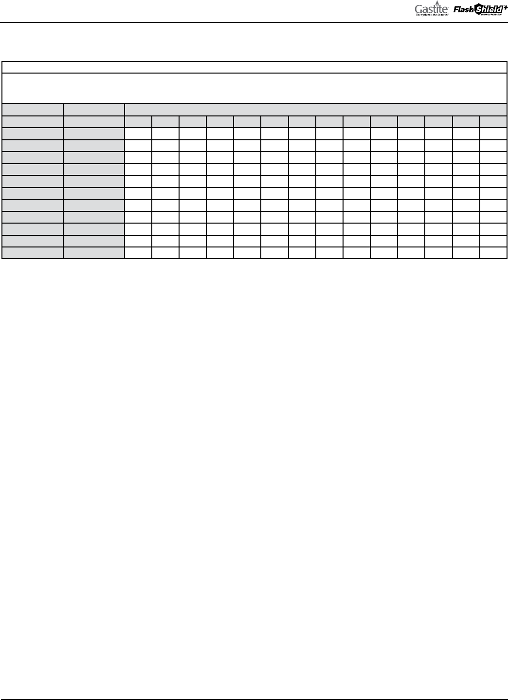
GASTITE DIVISION, TITEFLEX CORPORATION / 1116 Vaughn Parkway / Portland, TN 37148
800.662.0208 / www.gastite.com / [email protected]
91
SECTION 7: SIZING TABLES & PRESSURE DROP CHARTS / JANUARY 2020
7.6 IRON PIPE CAPACITY TABLES
Table 7-23
Maximum Capacity of Steel IPS Pipe in Cubic Feet Per Hour
with a Gas Pressure of 0.5 PSI or Less and a Pressure Drop of 0.5"WC
(based on a 0.60 specific gravity gas)
Internal Nominal Iron Run Length (ft)
Diameter (in.) Pipe Size (in.) 10 20 30 40 50 60 70 80 90 100 125 150 175 200
0.364 1/4" 43 29 24 20 18 16 15 14 13 12 11 10 9 8
0.493 3/8" 95 65 52 45 40 36 33 31 29 27 24 22 20 19
0.622 1/2" 175 120 97 82 73 66 61 57 53 50 44 40 37 35
0.824 3/4" 360 250 200 170 151 138 125 118 110 103 93 84 77 72
1.049 1" 680 465 375 320 285 260 240 220 205 195 175 160 145 135
1.38 1-1/4" 1400 950 770 660 580 530 490 460 430 400 360 325 300 280
1.61 1-1/2" 2100 1460 1180 990 900 810 750 690 650 620 550 500 460 430
2.067 2" 3950 2750 2200 1900 1680 1520 1400 1300 1220 1150 1020 950 850 800
2.469 2-1/2" 6300 4350 3520 3000 2650 2400 2250 2050 1950 1850 1650 1500 1370 1280
3.068 3" 11000 7700 6250 5300 4750 4300 3900 3700 3450 3250 2950 2650 2450 2280
4.026 4" 23000 15800 12800 10900 9700 8800 8100 7500 7200 6700 6000 5500 5000 4600
Table reproduced from National Fuel Gas Code NFPA-54.

GASTITE DIVISION, TITEFLEX CORPORATION / 1116 Vaughn Parkway / Portland, TN 37148
800.662.0208 / www.gastite.com / [email protected]
92
SECTION 7: SIZING TABLES & PRESSURE DROP CHARTS / JANUARY 2020
7.7 IRON PIPE PRESSURE DROP PER FOOT TABLES
Table 7-24 (Sheet 1 of 4)
Steel IPS Pressure Drop Tables
Pressure drop per foot in inches of water column (based on Natural Gas of 0.60 specific gravity)
CFH 1/2" 3/4" 1" 1-1/4" 1-1/2" 2" 2-1/2"
10 0.0 0.0 0.0 0.0 0.000 0.000 0.000
20 0.001 0.000 0.000 0.000 0.000 0.000 0.000
30 0.002 0.001 0.000 0.000 0.000 0.000 0.000
40 0.003 0.001 0.000 0.000 0.000 0.000 0.000
50 0.005 0.001 0.000 0.000 0.000 0.000 0.000
60 0.007 0.002 0.001 0.000 0.000 0.000 0.000
70 0.010 0.002 0.001 0.000 0.000 0.000 0.000
80 0.012 0.003 0.001 0.000 0.000 0.000 0.000
90 0.015 0.004 0.001 0.000 0.000 0.000 0.000
100 0.019 0.005 0.001 0.000 0.000 0.000 0.000
110 0.022 0.006 0.002 0.000 0.000 0.000 0.000
120 0.026 0.007 0.002 0.001 0.000 0.000 0.000
130 0.030 0.008 0.002 0.001 0.000 0.000 0.000
140 0.035 0.009 0.003 0.001 0.000 0.000 0.000
150 0.039 0.010 0.003 0.001 0.000 0.000 0.000
160 0.044 0.011 0.004 0.001 0.000 0.000 0.000
170 0.050 0.013 0.004 0.001 0.000 0.000 0.000
180 0.055 0.014 0.004 0.001 0.001 0.000 0.000
190 0.061 0.016 0.005 0.001 0.001 0.000 0.000
200 0.067 0.017 0.005 0.001 0.001 0.000 0.000
225 0.083 0.021 0.007 0.002 0.001 0.000 0.000
250 0.101 0.026 0.008 0.002 0.001 0.000 0.000
275 0.121 0.031 0.010 0.003 0.001 0.000 0.000
300 0.142 0.036 0.011 0.003 0.001 0.000 0.000
325 0.164 0.042 0.013 0.003 0.002 0.000 0.000
350 0.189 0.048 0.015 0.004 0.002 0.001 0.000
375 0.214 0.055 0.017 0.004 0.002 0.001 0.000
400 0.241 0.062 0.019 0.005 0.002 0.001 0.000
425 0.270 0.069 0.021 0.006 0.003 0.001 0.000
450 0.300 0.077 0.024 0.006 0.003 0.001 0.000
475 0.332 0.085 0.026 0.007 0.003 0.001 0.000
500 0.365 0.093 0.029 0.008 0.004 0.001 0.000
525 0.399 0.102 0.032 0.008 0.004 0.001 0.000
550 0.435 0.111 0.034 0.009 0.004 0.001 0.001
575 0.472 0.121 0.037 0.010 0.005 0.001 0.001
600 0.511 0.131 0.041 0.011 0.005 0.002 0.001
625 0.551 0.141 0.044 0.012 0.005 0.002 0.001
650 0.592 0.151 0.047 0.012 0.006 0.002 0.001
675 0.635 0.162 0.050 0.013 0.006 0.002 0.001
700 0.679 0.174 0.054 0.014 0.007 0.002 0.001
725 0.724 0.185 0.057 0.015 0.007 0.002 0.001
750 0.771 0.197 0.061 0.016 0.008 0.002 0.001
775 0.820 0.210 0.065 0.017 0.008 0.002 0.001
800 0.869 0.222 0.069 0.018 0.009 0.003 0.001
Tables calculated from National Fuel Gas Code NFPA-54 tables. 7.7

GASTITE DIVISION, TITEFLEX CORPORATION / 1116 Vaughn Parkway / Portland, TN 37148
800.662.0208 / www.gastite.com / [email protected]
93
SECTION 7: SIZING TABLES & PRESSURE DROP CHARTS / JANUARY 2020
Table 7-24 (Sheet 2 of 4)
Steel IPS Pressure Drop Tables
Pressure drop per foot in inches of water column (based on Natural Gas of 0.60 specific gravity)
CFH 1/2" 3/4" 1" 1-1/4" 1-1/2" 2" 2-1/2"
825 0.920 0.235 0.073 0.019 0.009 0.003 0.001
850 0.972 0.249 0.077 0.020 0.010 0.003 0.001
875 1.026 0.262 0.081 0.022 0.010 0.003 0.001
900 1.080 0.276 0.086 0.023 0.011 0.003 0.001
925 1.137 0.291 0.090 0.024 0.011 0.003 0.001
950 1.194 0.305 0.095 0.025 0.012 0.004 0.001
975 1.253 0.320 0.099 0.026 0.012 0.004 0.002
1000 1.313 0.336 0.104 0.028 0.013 0.004 0.002
1050 1.437 0.367 0.114 0.030 0.014 0.004 0.002
1100 1.566 0.400 0.124 0.033 0.016 0.005 0.002
1150 1.700 0.435 0.135 0.036 0.017 0.005 0.002
1200 1.839 0.470 0.146 0.039 0.018 0.005 0.002
1250 1.983 0.507 0.157 0.042 0.020 0.006 0.002
1300 2.132 0.545 0.169 0.045 0.021 0.006 0.003
1350 2.286 0.585 0.181 0.048 0.023 0.007 0.003
1400 2.445 0.625 0.194 0.051 0.024 0.007 0.003
1450 2.609 0.667 0.207 0.055 0.026 0.008 0.003
1500 2.778 0.710 0.220 0.058 0.028 0.008 0.003
1550 2.951 0.755 0.234 0.062 0.029 0.009 0.004
1600 3.130 0.800 0.248 0.066 0.031 0.009 0.004
1650 3.313 0.847 0.263 0.070 0.033 0.010 0.004
1700 3.501 0.895 0.278 0.073 0.035 0.010 0.004
1750 3.693 0.945 0.293 0.078 0.037 0.011 0.005
1800 3.891 0.995 0.309 0.082 0.039 0.012 0.005
1850 4.093 1.047 0.325 0.086 0.041 0.012 0.005
1900 4.300 1.100 0.341 0.090 0.043 0.013 0.005
1950 4.511 1.154 0.358 0.095 0.045 0.013 0.006
2000 4.727 1.209 0.375 0.099 0.047 0.014 0.006
2050 4.948 1.266 0.393 0.104 0.049 0.015 0.006
2100 5.173 1.323 0.410 0.109 0.051 0.015 0.006
2150 5.403 1.382 0.429 0.113 0.054 0.016 0.007
2200 5.638 1.442 0.447 0.118 0.056 0.017 0.007
2250 5.877 1.503 0.466 0.123 0.058 0.017 0.007
2300 6.121 1.565 0.486 0.128 0.061 0.018 0.008
2350 6.369 1.629 0.505 0.134 0.063 0.019 0.008
2400 6.622 1.694 0.525 0.139 0.066 0.020 0.008
2450 6.879 1.759 0.546 0.144 0.068 0.020 0.009
2500 7.141 1.826 0.567 0.150 0.071 0.021 0.009
2550 7.407 1.894 0.588 0.155 0.074 0.022 0.009
2600 7.677 1.964 0.609 0.161 0.076 0.023 0.010
2650 7.953 2.034 0.631 0.167 0.079 0.024 0.010
2700 8.232 2.105 0.653 0.173 0.082 0.024 0.010
2750 8.516 2.178 0.676 0.179 0.085 0.025 0.011
2800 8.805 2.252 0.699 0.185 0.088 0.026 0.011
Tables calculated from National Fuel Gas Code NFPA-54 tables.

GASTITE DIVISION, TITEFLEX CORPORATION / 1116 Vaughn Parkway / Portland, TN 37148
800.662.0208 / www.gastite.com / [email protected]
94
SECTION 7: SIZING TABLES & PRESSURE DROP CHARTS / JANUARY 2020
Table 7-24 (Sheet 3 of 4)
Steel IPS Pressure Drop Tables
Pressure drop per foot in inches of water column (based on Natural Gas of 0.60 specific gravity)
CFH 1/2" 3/4" 1" 1-1/4" 1-1/2" 2" 2-1/2"
2850 9.097 2.327 0.722 0.191 0.090 0.027 0.011
2900 9.395 2.403 0.745 0.197 0.093 0.028 0.012
2950 9.696 2.480 0.769 0.204 0.096 0.029 0.012
3000 10.002 2.558 0.794 0.210 0.099 0.030 0.013
3050 10.312 2.638 0.818 0.216 0.103 0.031 0.013
3100 10.627 2.718 0.843 0.223 0.106 0.031 0.013
3150 10.946 2.800 0.868 0.230 0.109 0.032 0.014
3200 11.269 2.882 0.894 0.237 0.112 0.033 0.014
3250 11.597 2.966 0.920 0.243 0.115 0.034 0.015
3300 11.929 3.051 0.946 0.250 0.119 0.035 0.015
3350 12.265 3.137 0.973 0.257 0.122 0.036 0.015
3400 12.606 3.224 1.000 0.265 0.125 0.037 0.016
3450 12.951 3.312 1.028 0.272 0.129 0.038 0.016
3500 13.300 3.402 1.055 0.279 0.132 0.039 0.017
3550 13.653 3.492 1.083 0.287 0.136 0.040 0.017
3600 3.583 1.112 0.294 0.139 0.041 0.018
3650 3.676 1.140 0.302 0.143 0.043 0.018
3700 3.770 1.169 0.309 0.147 0.044 0.018
3750 3.864 1.199 0.317 0.150 0.045 0.019
3800 3.960 1.228 0.325 0.154 0.046 0.019
3850 4.057 1.258 0.333 0.158 0.047 0.020
3900 4.155 1.289 0.341 0.161 0.048 0.020
3950 4.254 1.320 0.349 0.165 0.049 0.021
4000 4.354 1.351 0.357 0.169 0.050 0.021
4050 4.455 1.382 0.366 0.173 0.052 0.022
4100 4.557 1.414 0.374 0.177 0.053 0.022
4150 4.660 1.446 0.382 0.181 0.054 0.023
4200 4.765 1.478 0.391 0.185 0.055 0.023
4250 4.870 1.511 0.400 0.189 0.056 0.024
4300 4.976 1.544 0.408 0.193 0.058 0.024
4350 5.084 1.577 0.417 0.198 0.059 0.025
4400 5.193 1.611 0.426 0.202 0.060 0.025
4450 5.302 1.645 0.435 0.206 0.061 0.026
4500 5.413 1.679 0.444 0.210 0.063 0.026
4550 5.524 1.714 0.453 0.215 0.064 0.027
4600 5.637 1.749 0.463 0.219 0.065 0.028
4650 5.751 1.784 0.472 0.224 0.067 0.028
4700 5.866 1.820 0.481 0.228 0.068 0.029
4750 5.982 1.856 0.491 0.233 0.069 0.029
4800 6.099 1.892 0.501 0.237 0.071 0.030
4850 6.216 1.928 0.510 0.242 0.072 0.030
4900 6.335 1.965 0.520 0.246 0.073 0.031
Tables calculated from National Fuel Gas Code NFPA-54 tables.

GASTITE DIVISION, TITEFLEX CORPORATION / 1116 Vaughn Parkway / Portland, TN 37148
800.662.0208 / www.gastite.com / [email protected]
95
SECTION 7: SIZING TABLES & PRESSURE DROP CHARTS / JANUARY 2020
Table 7-24 (Sheet 4 of 4)
Steel IPS Pressure Drop Tables
Pressure drop per foot in inches of water column (based on Natural Gas of 0.60 specific gravity)
CFH 1/2" 3/4" 1" 1-1/4" 1-1/2" 2" 2-1/2"
4950 6.455 2.003 0.530 0.251 0.075 0.032
5000 6.577 2.040 0.540 0.256 0.076 0.032
5100 6.822 2.116 0.560 0.265 0.079 0.033
5200 7.071 2.194 0.580 0.275 0.082 0.035
5300 7.324 2.272 0.601 0.285 0.085 0.036
5400 7.582 2.352 0.622 0.295 0.088 0.037
5500 7.843 2.433 0.644 0.305 0.091 0.038
5600 8.109 2.516 0.666 0.315 0.094 0.040
5700 8.379 2.599 0.688 0.326 0.097 0.041
5800 8.652 2.684 0.710 0.336 0.100 0.042
5900 8.930 2.770 0.733 0.347 0.103 0.044
6000 9.212 2.858 0.756 0.358 0.107 0.045
6100 9.498 2.946 0.780 0.369 0.110 0.046
6200 9.788 3.036 0.803 0.380 0.113 0.048
6300 10.081 3.127 0.827 0.392 0.117 0.049
6400 10.379 3.220 0.852 0.403 0.120 0.051
6500 10.681 3.313 0.877 0.415 0.124 0.052
6600 10.987 3.408 0.902 0.427 0.127 0.054
6700 11.296 3.504 0.927 0.439 0.131 0.055
6800 11.610 3.602 0.953 0.451 0.134 0.057
6900 11.927 3.700 0.979 0.464 0.138 0.058
7000 12.249 3.800 1.005 0.476 0.142 0.060
7100 12.574 3.901 1.032 0.489 0.146 0.061
7200 12.904 4.003 1.059 0.502 0.149 0.063
7300 13.237 4.106 1.086 0.515 0.153 0.065
7400 13.574 4.211 1.114 0.528 0.157 0.066
7500 4.317 1.142 0.541 0.161 0.068
7750 4.586 1.213 0.575 0.171 0.072
8000 4.864 1.287 0.609 0.181 0.077
8250 5.148 1.362 0.645 0.192 0.081
8500 5.440 1.439 0.682 0.203 0.086
8750 5.740 1.519 0.719 0.214 0.090
9000 6.046 1.600 0.758 0.226 0.095
9250 6.361 1.683 0.797 0.237 0.100
9500 6.682 1.768 0.837 0.249 0.105
9750 7.011 1.855 0.878 0.262 0.111
10000 7.346 1.944 0.921 0.274 0.116
11000 8.762 2.318 1.098 0.327 0.138
12000 10.291 2.723 1.289 0.384 0.162
13000 11.931 3.157 1.495 0.445 0.188
14000 13.683 3.620 1.715 0.511 0.216
15000 4.113 1.948 0.580 0.245
Tables calculated from National Fuel Gas Code NFPA-54 tables.
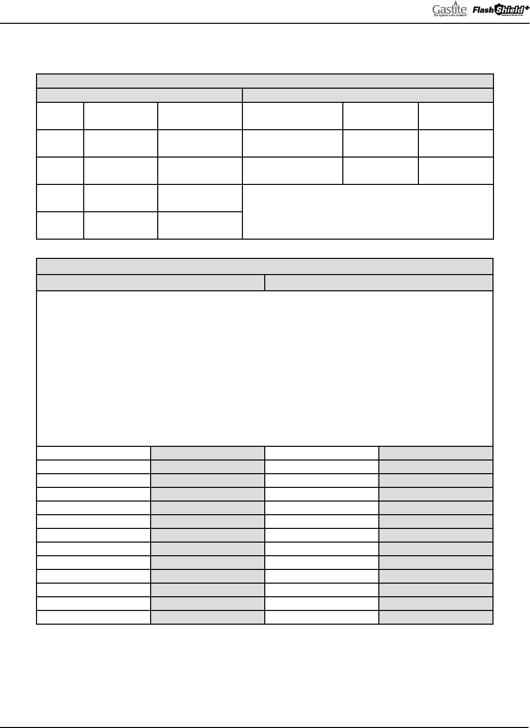
GASTITE DIVISION, TITEFLEX CORPORATION / 1116 Vaughn Parkway / Portland, TN 37148
800.662.0208 / www.gastite.com / [email protected]
96
SECTION 7: SIZING TABLES & PRESSURE DROP CHARTS / JANUARY 2020
7.8 REFERENCE DATA
Table 7-25
Pressure Conversion Factors Fuel Gas Information
1/4 PSI = 6.921"WC = (approx. 7"WC)
Natural Gas Propane
1/2 PSI = 13.842"WC = (approx. 14"WC) BTU per Cubic Foot = 1000 2516
1 PSI = 27.684"WC = (approx. 28"WC) Specific Gravity = 0.60 1.52
2 PSI = 55.368"WC = (approx. 56"WC)
Note: “Pressure Drop Curves for Gastite/FlashShield+ CSST” are
expressed in terms of Cubic Feet per Hour (CFH). To determine the
CFH for Natural Gas, divide the BTU load by 1000. To determine
the CFH for Propane, divide the BTU load by 2516.
5 PSI = 138.42"WC = (approx. 140"WC)
Table 7-26
Pressure Conversion Factors Fuel Gas Information
Gas piping systems that are to be supplied with gas of a specific gravity other than 0.60 shall apply a specific gravity factor.
e conversion is accomplished by multiplying the capacities given in the tables, charts and graphs by the appropriate
multiplier from the table below. In case the exact specific gravity does not appear in the table, choose the next higher value
shown. Check with the local gas utility or supplier for the correct specific gravity.
Options:
1. Using Table A-5 the flow capacity of 1/2" CSST at 50 ft, for natural gas with a specific gravity of 0.60 is 266
CFH. At a specific gravity of 0.65 the resultant value in the table will be 255 CFH (266 x 0.96).
or
2. A furnace rated at 80,000 BTUH natural gas with a specific gravity of 0.60 will be rated at 76,800 BTUH natural
gas with a specific gravity of 0.65 (80,000/0.96).
Specific Gravity Multiplier Specific Gravity Multiplier
0.35 1.31 1.00 0.78
0.40 1.23 1.10 0.74
0.45 1.16 1.20 0.71
0.50 1.10 1.30 0.68
0.55 1.04 1.40 0.66
0.60 1.00 1.50 0.63
0.65 0.96 1.60 0.61
0.70 0.93 1.70 0.59
0.75 0.90 1.80 0.58
0.80 0.87 1.90 0.56
0.85 0.84 2.00 0.55
0.90 0.82 2.10 0.54

GASTITE DIVISION, TITEFLEX CORPORATION / 1116 Vaughn Parkway / Portland, TN 37148
800.662.0208 / www.gastite.com / [email protected]
97
SECTION 8: DEFINITIONS / JANUARY 2020
SECTION 8.0 DEFINITIONS
APPLIANCE (EQUIPMENT) – Any device which utilizes gas as a fuel or raw material to produce light, heat, power,
refrigeration or air conditioning.
APPROVED – Acceptable to the authority having jurisdiction.
ARC RESISTANT PROTECTIVE JACKET (AR) – A protective jacket over the CSST which has been tested and listed
to ANSI LC1 Sec. 5.16, and ICC-ES PMG LC1027, for electrical arcing protection performance.
ARC-TRAP™ – A feature of XR3 REV2-series fittings which enables unintended electrical current of significant voltage on
protective jacket to conduct to brass fittings.
AUTHORITY HAVING JURISDICTION – e organization, office or individual responsible for “approving”
equipment, an installation or procedure.
BONDING (BONDED) – e permanent joining of metallic parts to form an electrically conductive path that
ensures electrical continuity and the capacity to conduct safely any current likely to be imposed. As per the National
Electrical Code.
CAPACITY, FLOW – As used in this standard, the amount of a specified gas that will flow through a specific length and
configuration of tubing, a manifold, fitting or other component at a specified pressure drop in a fixed period of time.
CONCEALED GAS TUBING – Gas tubing, which, when in place in a finished building, would require removal of
permanent construction to gain access to the piping.
CONNECTOR, GAS APPLIANCE – A factory-fabricated assembly of gas conduit and related fittings designed to
convey gaseous fuel, and used for making connections between a gas supply piping outlet and the gas to an appliance.
It is equipped at each end for attachment to standard taper pipe threads.
CONTINUOUS METALLIC SYSTEMS – Potential pathways for electricity to ground i.e. metallic chimney and vents,
metallic ducting and piping, insulated or jacketed electrical cables and wires.
DIRECT BONDING – Bonding, as above, where the electrical connection is made using a clamp and wire at the
piping connected directly to the existing electrical grounding system. Refer to Section 4.10 Electrical Bonding of
FlashShield
+
CSST.
EFFECTIVE GROUND-FAULT CURRENT PATH – An intentionally constructed, permanent, low impedance
electrically conductive path designed and intended to carry under ground fault conditions from the point of a ground fault
on a wiring system to the electrical supply source.
EQUIVALENT HYDRAULIC DIAMETER (EHD) – A theoretical size, which reflects the hydraulic performance of the
tubing. It is not true physical measurement.
EXPOSED GAS TUBING – Gas tubing which will be in view in the finished structure.
FUEL GAS – A commonly distributed gas used for fuel such as natural gas, manufactured gas, undiluted liquefied
petroleum gas (vapor phase only), liquefied petroleum gas-air mixtures of these gases (includes propane and butane).
GAS UTILIZATION EQUIPMENT – Any device that utilizes gas as a fuel or raw material or both.
INCHES OF WATER COLUMN ("WC) – Method of pressure measured in inches of water column by a manometer or
pressure gauge. Commonly used in the gas industry when the pressure is less than 1 PSI.
INSULATIVE POLYMER COVER – e outer jacket is designed and tested to protect the CSST from electrical system
fault-current arcs.
JACKETLOCK™ – A feature of XR-series fittings which enables fitting to capture polymer jacket, protecting CSST from
corrosive threats.

GASTITE DIVISION, TITEFLEX CORPORATION / 1116 Vaughn Parkway / Portland, TN 37148
800.662.0208 / www.gastite.com / [email protected]
98
SECTION 8: DEFINITIONS / JANUARY 2020
LEAK TEST SOLUTION – A solution of commercial leak-testing fluids may be used. e use of soap buds or household
detergents and water is not considered a satisfactory leak-test fluid for a bubble test, because of a lack of sensitivity due to
masking by foam. e fluid should be capable of being applied free of bubbles so that a bubble appears only at a leak. e
fluid selected should not bubble except in response to a leak.
LISTED – Equipment or materials including a list published by an organization acceptable to the authority having
jurisdiction and concerned with product evaluation that maintains periodic inspection of production of listed equipment
or materials and whose listing states either that the equipment or materials meets appropriate standards or has been tested
and found suitable for use in a specified manner.
LOCKUP PRESSURE, REGULATOR – e system pressure, immediately downstream of the regulator, at which the
regulator valve will completely close (leak tight) under no-flow conditions to prevent the downstream pressure from
exceeding a predetermined level.
MAXIMUM ACTUAL OPERATING PRESSURE – e maximum pressure existing in a piping system during a normal
annual operating cycle.
OVER-PRESSURE PROTECTION DEVICE (OPD) – System component that is intended to protect all downstream
components from high pressures in the event of a system failure. OPDs are required in gas systems using more than 2 PSI
line pressure.
PIPING SYSTEM – As used in this standard, an assembly of corrugated stainless steel tubing and tubing connection
fittings, intended for field assembly and installation in residential or commercial buildings to distribute fuel gas to gas
utilization equipment within the building. e piping system may also include a gas pressure regulator(s), a shutoff
valve(s), tube shielding devices, distribution manifold(s), and other approved devices or components.
PLENUM – A plenum is an enclosed portion of the building structure that is designed to allow air movement, and
thereby serve as part of an air distribution system.
PRESSURE DROP – e loss in static pressure of flowing fuel gas due to friction or other flow resistance in tubing,
fittings, valves, regulators, or other devices in the piping system.
QUALIFIED INSTALLER – Any individual, firm, corporation or company which either in person or through a
representative is engaged in and is responsible for the installation or replacement of building gas piping systems, who
is experienced in such work, familiar with all precautions required, and has complied with all the requirements of the
authority having jurisdiction.
QUICK-DISCONNECT DEVICE – A hand-operated device which provides a means for connecting and disconnecting
an appliance or an appliance connector to a gas supply, and which is equipped with an automatic means to shut off the gas
supply when the device is disconnected.
REGULATOR, PRESSURE – A device placed in a gas line for reducing, controlling and maintaining the pressure in that
portion of the piping system downstream of the device.
SHIELDING DEVICE – A component of the piping system used to protect the installed corrugated tubing from
accidental puncture by nails, screws or similar hardware at concealed tubing support points.
STRIKER PLATE – A special type of shielding device used when concealed tubing is run through wall studs, floor and
ceiling joists or other structural members where tubing movement is restricted.
VALVE, SHUTOFF – A device used in piping to control the gas supply to any section of the piping system or to an
appliance.
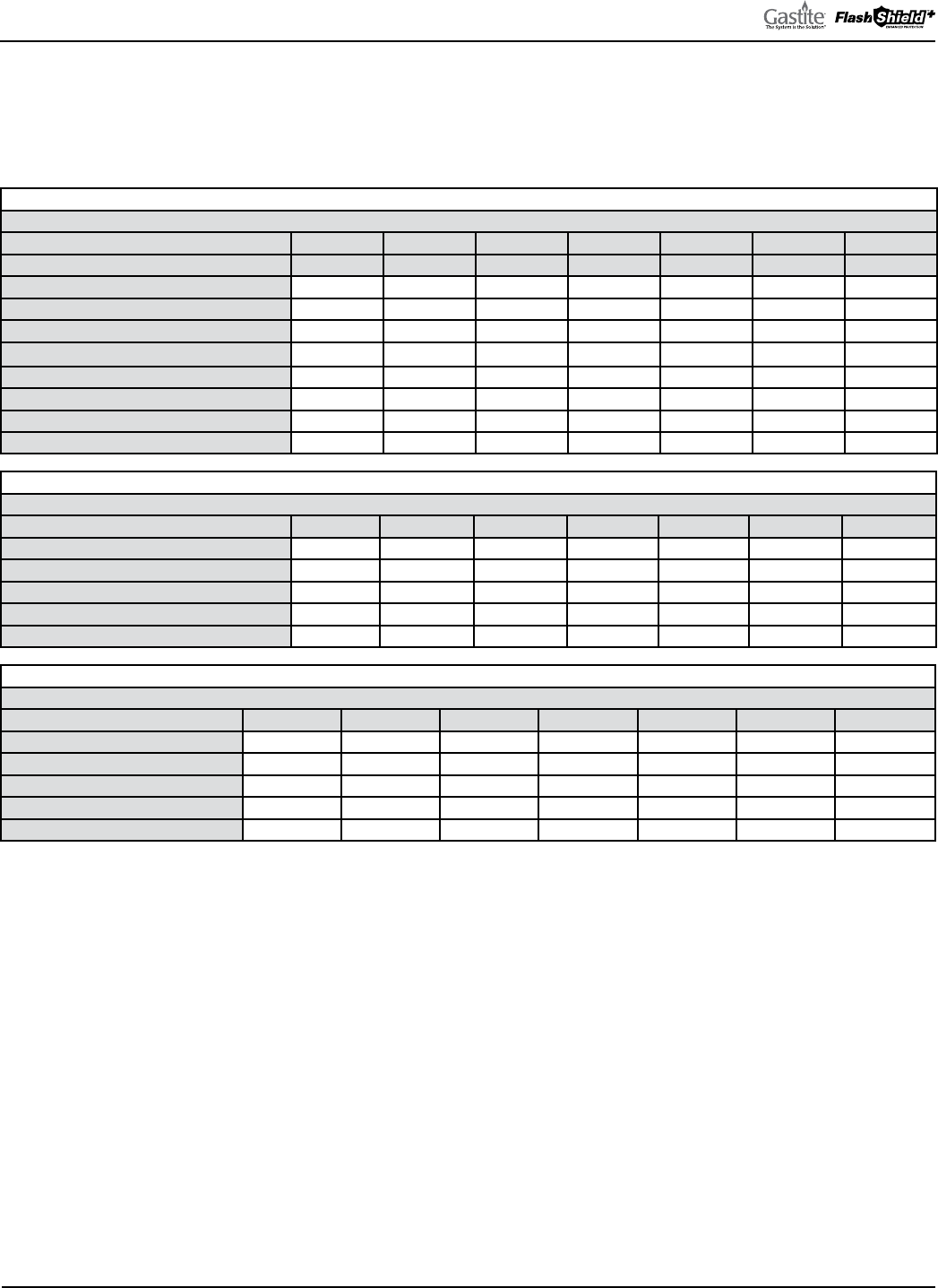
GASTITE DIVISION, TITEFLEX CORPORATION / 1116 Vaughn Parkway / Portland, TN 37148
800.662.0208 / www.gastite.com / [email protected]
99
SECTION 9: DIMENSIONAL & TECHNICAL REFERENCE DATA / JANUARY 2020
SECTION 9.0
DIMENSIONAL & TECHNICAL REFERENCE DATA
9.1 GASTITE AND FLASHSHIELD
+
DIMENSIONAL AND TECHNICAL REFERENCE DATA
Table 9-1
Corrugated Stainless Steel Tubing – Dimensional Values
Size (Nom. I.D.) 3/8" 1/2" 3/4" 1" 1-1/4" 1-1/2" 2"
FlashShield
+
™ Part Number
-- FSP-8 FSP-11 FSP-16 FSP-20 FSP-24 FSP-32
Gastite® Part Number S93-6A4 S93-8A4 S93-11B4 S93-16A4 S93-20A4 S93-24A4 S93-32A4
Equivalent Hydraulic Diameter (EHD) 13 19 23 31 37 48 60
Inside Nominal Diameter (in.) 0.39 0.58 0.75 1.04 1.25 1.48 1.98
Outside Diameter (w/o jacket) (in.) 0.51 0.72 0.92 1.26 1.50 1.75 2.32
FlashShield
+
™ Outside Diameter, w/jacket (in.)
-- 0.78 1.0 1.33 1.57 1.82 2.40
Gastite® Outside Diameter, w/jacket (in.) 0.56 0.76 0.98 1.30 1.55 1.79 2.40
Length of Standard Reels (Ft) 50-1,000 25-1,000 25-500 50-300 50-300 50-300 50-150
CSST Wall ickness (in.) 0.01 0.01 0.01 0.01 0.011 0.011 0.012
Table 9-2
"XR" Series Straight Fitting – Dimensional Values
Fits CSST Size 3/8" 1/2" 3/4" 1" 1-1/4" 1-1/2" 2"
XR Series Fitting Part Number XR2FTG-6 XR3FTG-8 XR3FTG-11 XR3FTG-16 XR3FTG-20 XR3FTG-24 XR3FTG-32
Pipe read (NPT) 1/2" 1/2" 3/4" 1" 1 1/4" 1-1/2" 2"
Adapter Hex Size 7/8" 1-1/8" 1-3/8" 1-3/4" 2" 2-5/16" 3"
Nut Hex Size 1" 1-1/4" 1-9/16" 1-15/16" 2-3/16" 2-9/16" 3-1/4"
Overall Length (in.) 1.93 1.61 1.82 2.01 2.15 2.32 2.66
Table 9-3
"XR" Series Termination Fitting – Dimensional Values
Fits CSST Size 3/8" 1/2" 3/4" 1" 1-1/4" 1-1/2" 2"
Fitting Part Number XR2TRM-6 XR3TRM-8 XR3TRM-11 XR3TRM-16 XR3TRM-20 XR3TRM-24 XR3TRM-32
Pipe read (NPT) 1/2" 1/2" 3/4" 1" 1-1/4" 1-1/2" 2"
Flange read (NPT) 1/2" 3/4" 1" 1-1/4" 1-1/2" 2" 2-1/2"
Square Flange Outside Dimension 2-5/8" 2-5/8" 2-5/8" 2-5/8" 3-1/4" 3-1/4" 3-5/8"
Mounting Hole Pattern Diameter 2-3/4" 2-3/4" 2-3/4" 2-3/4" 3-1/4" 3-1/4" 4"

GASTITE DIVISION, TITEFLEX CORPORATION / 1116 Vaughn Parkway / Portland, TN 37148
800.662.0208 / www.gastite.com / [email protected]
100
SECTION 9: DIMENSIONAL & TECHNICAL REFERENCE DATA / JANUARY 2020
9.2.A GASTITE
®
SPECIFICATION SHEET
ALL SYSTEM COMPONENTS ARE CSA APPROVED
SYSTEM PERFORMANCE
PRESSURE RATING
Tubing:
Maximum Approved Operating Pressure 25 PSI
Tubing Minimum Burst Pressure 1,500 PSI
Maximum Test Pressure 3/8", 1/2" & 3/4": 150 PSI
1": 125 PSI
1-1/4": 100 PSI
1-1/2": 50 PSI
2": 40 PSI
TEMPERATURE LIMITS
Stainless Steel Melting Point: 2,400°F
Plastic Jacket Melting Point: 205°F
Plastic Jacket Minimum Installation Temp (for bending): -40°F
Plastic Jacket Maximum Operating Temp: 160°F
SYSTEM MATERIALS
CORRUGATED STAINLESS STEEL TUBING
Tubing: ASTM A240 Type 304 Stainless Steel
Jacket:
Electrically insulative and UV resistant polymer, complying with ASTM E84 and
CAN/ULC-S102.2 25/50.
FITTING MATERIAL
Mechanical Joint Fitting:
Adapter: CA360 Brass
Nut: CA360 Brass
Split Bushings: CA360 Brass
Termination Fitting:
Adapter: CA360 Brass
Nut: CA360 Brass
Split Bushing: CA360 Brass
Flange: Square Flange – Steel with Zinc Coating
PROTECTION DEVICES
Striker Plates: 16 Gage AISI 1050 Carbon Steel Hardened to Rc 45 with Black Oil and Phosphate Coating
Floppy Conduit: Strip Wound Interlocking Steel (Heavy Wall)
ACCESSORIES
Valves: Meet requirements of ANSI/ASME B16.33 (125 PSI) or AGA 3-88 (5 PSI)
Regulators: Gas line pressure regulator std. ANSI/CGA Z21.80, CGA-6.22 with vent limiting device
Manifolds Cast: ASTM A47 32510 Malleable Iron
Welded: Welded IPS Schedule 40

GASTITE DIVISION, TITEFLEX CORPORATION / 1116 Vaughn Parkway / Portland, TN 37148
800.662.0208 / www.gastite.com / [email protected]
101
SECTION 9: DIMENSIONAL & TECHNICAL REFERENCE DATA / JANUARY 2020
9.2.B FLASHSHIELD+
™
SPECIFICATION SHEET
ALL SYSTEM COMPONENTS ARE CSA APPROVED
SYSTEM PERFORMANCE
PRESSURE RATING
Tubing:
Maximum Approved Operating Pressure 25 PSI
Tubing Minimum Burst Pressure 1,500 PSI
Maximum Test Pressure 1/2" & 3/4": 150 PSI
1": 125 PSI
1-1/4": 100 PSI
1-1/2": 50 PSI
2": 40 PSI
TEMPERATURE LIMITS
Stainless Steel Melting Point: 2,400°F
Plastic Jacket Melting Point: 205°F
Plastic Jacket Minimum Installation Temp (for bending): -40°F
Plastic Jacket Maximum Operating Temp: 160°F
SYSTEM MATERIALS
CORRUGATED STAINLESS STEEL TUBING
Tubing: ASTM A240 Type 304 Stainless Steel
Jacket: Electrically insulative and UV resistant polymer, complying with ASTM E84 and
CAN/ULC - S102.2 25/50.
FITTING MATERIAL
Mechanical Joint Fitting:
Adapter: CA360 Brass
Nut: CA360 Brass
Split Bushings: CA360 Brass
PROTECTION DEVICES
Striker Plates: 16 Gage AISI 1050 Carbon Steel Hardened to Rc 45 with Black Oil and Phosphate Coating
Floppy Conduit: Strip Wound Interlocking Steel (Heavy Wall)
ACCESSORIES
Valves: Meet requirements of ANSI/ASME B16.33 (125 PSI) or AGA 3-88 (5 PSI)
Regulators: Gas line pressure regulator std. ANSI/CGA Z21.80, CGA-6.22 with vent limiting device
Manifolds Cast: ASTM A47 32510 Malleable Iron
Welded: Welded IPS Schedule 40

GASTITE DIVISION, TITEFLEX CORPORATION / 1116 Vaughn Parkway / Portland, TN 37148
800.662.0208 / www.gastite.com / [email protected]
102
SECTION 10: WARRANTY / JANUARY 2020
SECTION 10.0 WARRANTY
WARRANTY
GASTITE
®
FLEXIBLE GAS PIPING SYSTEM
FLASHSHIELD
+
™
FLEXIBLE GAS PIPING SYSTEM
Gastite Division warrants its products to be free from any defect of workmanship and material. Should any such defects be
discovered, the questionable product must be returned to Gastite Division. If, upon inspection, the part proves to be defective,
Gastite Division will furnish a replacement, or, at its option, repair the part.
is warranty shall not apply to any part or parts of the Gastite®/FlashShield
+
™ Flexible Gas Piping System product if it has
been installed, altered, repaired or misused, through negligence or otherwise, in a way that in the opinion of Gastite Division
affects the reliability of, or detracts from, the performance of the product. Nor does this warranty cover replacements or repairs
necessitated by loss or damage resulting from any cause beyond the control of Gastite Division, including but not limited to,
acts of God, acts of government, floods and fires.
e obligation of Gastite Division under this warranty is limited, at Gastite Division’s discretion, to 1) making a replacement
part available, 2) the repair of the defective part, or 3) refund of purchase price. is does not include the furnishing of any
labor involved or connected therewith, such as that required to diagnose trouble or to remove or install any such product, nor
does it include responsibility for any transportation expenses or any damages or losses incurred in transportation in connection
therewith.
THE FOREGOING IS IN LIEU OF ANY OTHER WARRANTIES EXPRESSED, IMPLIED OR STATUTORY,
INCLUDING, WITHOUT LIMITATION, THE IMPLIED WARRANTY OF MERCHANTABILITY, AND GASTITE
DIVISION NEITHER ASSUMES NOR AUTHORIZES ANY PERSON TO ASSUME FOR GASTITE DIVISION ANY
OTHER OBLIGATION OR LIABILITY IN CONNECTION WITH THE SALE OF ITS PRODUCTS
INSTALLATION REQUIREMENTS
1) Installation must be performed strictly in accordance with local plumbing and/or building codes, and in accordance with
Gastite®/FlashShield
+
™ Design and Installation Guide.
2) Installation must be performed by an installer who has successfully completed a training program recognized by Gastite
Division and has been issued a Certification Card. Certifications are available through qualified distributors, and at
www.gastite.com.
3) Pressure testing must be performed during rough construction with piping system exposed.
4) Gastite Division assumes no responsibility for product or labor for any system which has been improperly installed.

GASTITE DIVISION, TITEFLEX CORPORATION / 1116 Vaughn Parkway / Portland, TN 37148
800.662.0208 / www.gastite.com / [email protected]
103
JANUARY 2020
NOTES
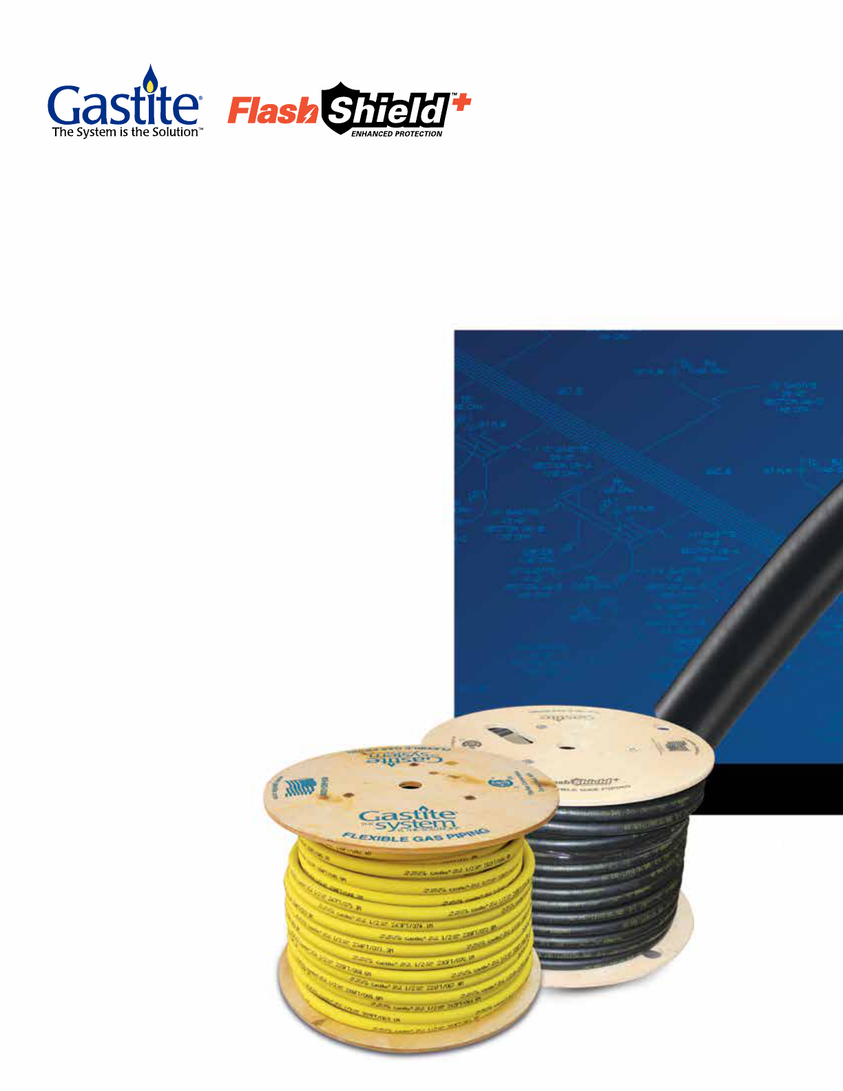
GASTITE DIVISION, TITEFLEX CORPORATION
1116 VAUGHN PARKWAY
PORTLAND, TN 37148
TOLL FREE: 800.662.0208
FAX: 615.325.9407
E-MAIL: [email protected]
WWW.GASTITE.COM
DI-GUIDE-CA
REV. JULY 2021
